RTK Series UC625 Annunciator
39
System DIL Switch Location and Functions
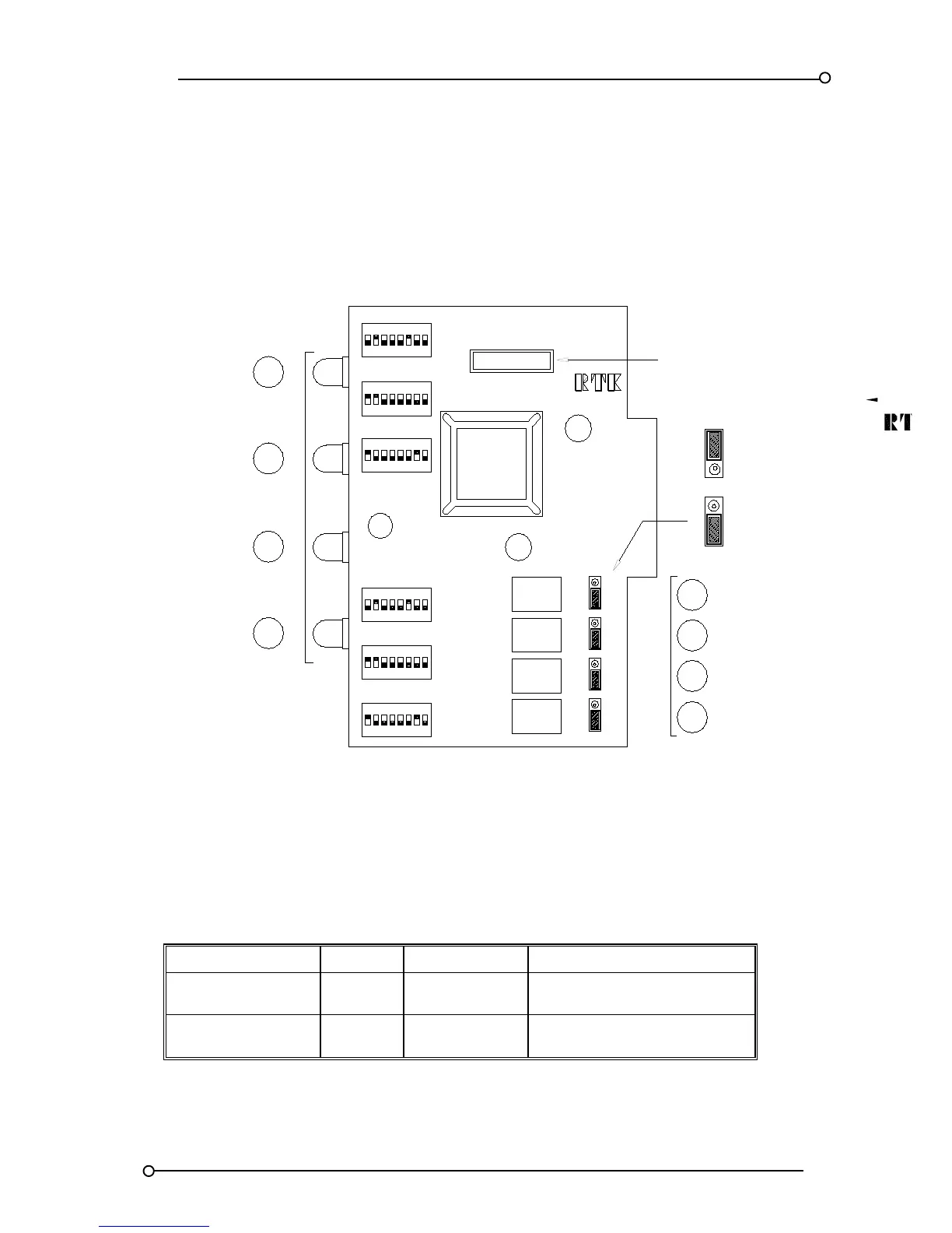
The (4) channel alarm cards part no CB5303POP* can be accessed after removal of the front panel
legend plate. Each (4) channel alarm card is equipped with six DIL switches which are used to select
various options as detailed in the following section. For further details on the operation of the alarm
sequences refer to the section headed sequences or the last page which summarises the switch
setting required for each ISA sequence.
ALARM CARD
C17
RL1
RL2
RL3
RL4
CHANNEL
SW4
AS5317-*
ASIC
SW1
3
SW3
1 2 54 6 87
NO
NORMALLY OPEN
NO
NORMALLY CLOSED
NC
NC
NO
NO
NC
NO
NC
NC
CONTACT SET
NO
NC
C16
FCV = 24VDC SET FOR 24VDC
SUPPLY VOLTAGE
LK1
LK2
LK3
LK4
LK4
1
2
3
4
1
2
3
4
CHANNEL
SW6
SW2
SW5
ON
8
1 2 3 4
ON
5 6 7
81 2 3 4
ON
5 6 7
8
ON
1 2 43 65 7
821 43
ON
65 7
81 2 43 65 7
ON
CB5303POP*
Alarm Card DIL Switch Location
Figure 10
DIL Switch Functions On Alarm Cards
Channels can be configured to suit individual requirements for the particular application, 6 x DIL
switches are provided in total 3 x for each pair of channels, as detailed below:-
FUNCTION CARD CHANNELS SWITCH
Input Response
Alarm
Alarm
1 and 2
3 and 4
SW1 Refer To Table 27
SW2 Refer To Table 27
Channel Features
Alarm
Alarm
1 and 2
3 and 4
SW3 and SW4 Refer To Fig 10
SW5 and SW6 Refer To Fig 11
Table 26

 Loading...