26
Common Alarm Relay Mode of Operation
Input Follower.
The common alarm relay will active when an alarm occurs and automatically return to normal when all
alarms have returned to the normal state.
Logic Follower.
The common alarm relay will active when an alarm occurs and only return to normal when all alarms
have returned to the normal state and the logic has been reset.
FUNCTION ALARM CARD CHANNEL
1 - 2 3 - 4
Input Follower SW4.S4 = ON SW6.S4 = ON
Logic Follower SW4.S4 = OFF SW6.S4 = OFF
Table 21
Sleep Mode
(Available on All units supplied after April 5
th
2004)
Sleep mode is typically used in sub station applications where the visual and audible outputs are
disabled during unmanned periods to reduce the drain on the associated station batteries. Whilst in
sleep mode the logic of the annunciator will continue to react in the normal way including the operation
of common alarm relays and individual channel signal duplicating relays only the drive signals to the
LED’s and audibles are disabled. An externally mounted two-pole switch is required to activate sleep
mode with 1 pole connected to the mute pushbutton input and the other pole connected to the reset
pushbutton input on the rear of the unit. The common return for both poles is OV-OP.
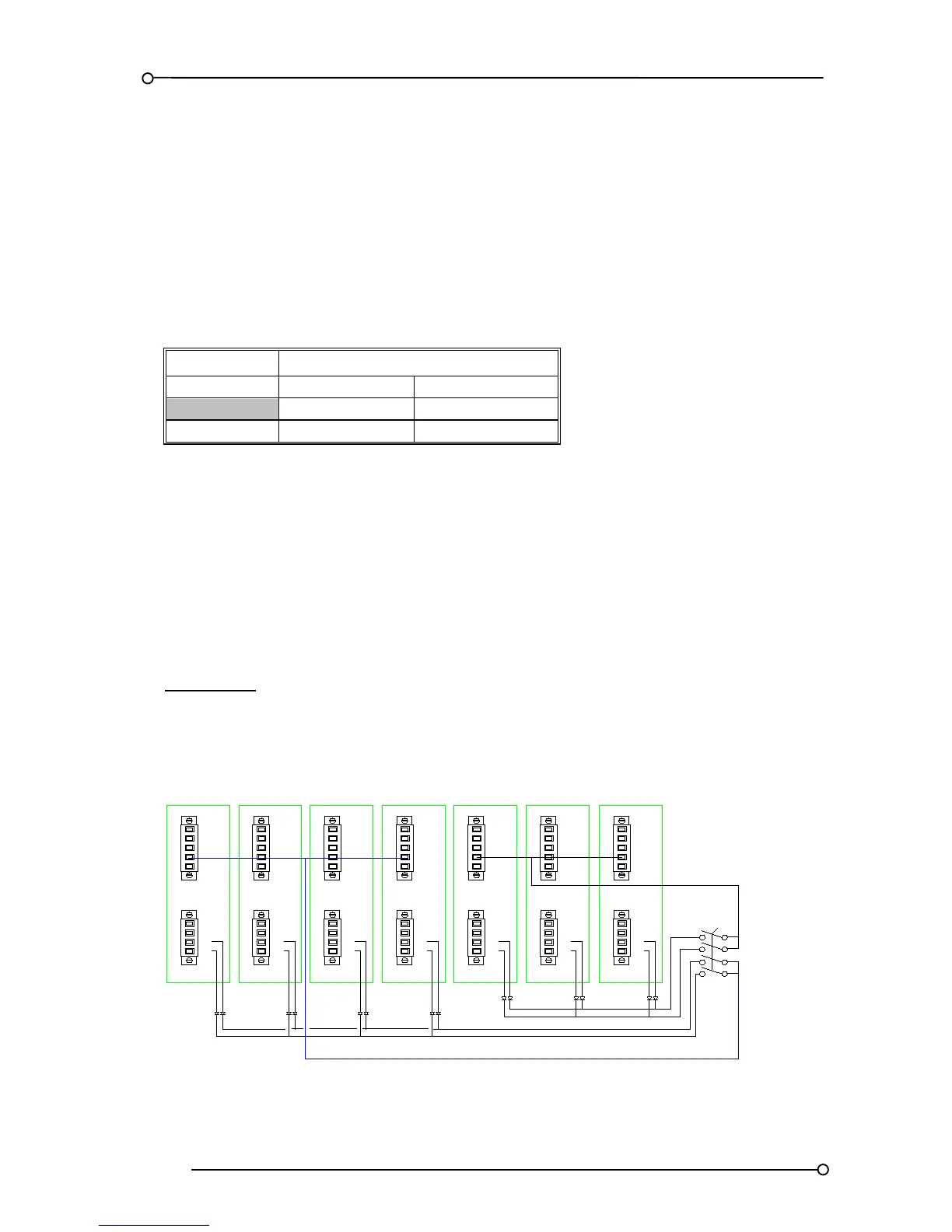
Please note:-
In typical Sub Station multiple UC625 Annunciators share a common sleep mode switch. In these
instances RTK recommend that general purpose isolation diodes are added in line to the remote
pushbutton inputs, additional poles are added to the sleep mode switch and inter panel links should be
divided equally as typically shown below.

 Loading...