BASIC OPERATION
FCM2041-U3 OPERATOR INTERFACE MANUAL | CHAPTER 1
1-6
Tree Structure In most menus, the FCM2041-U3 uses a tree structure to display the elements of
the system. Components connected to a device are children of that device; the
module connected just above the device is its parent. This tree structure closely
resembles the physical arrangement of elements used in the Zeus programming
tool.
Devices that have been organized into groups using the Zeus programming tool
appear on the tree structure in the hierarchy of highest to lowest with the corre-
sponding default names of: Campus (L5), Building (L4), Floor (L3), Area (L2), Zone
(L1). The default names can be changed in Zeus.
Devices that are not in groups are considered to be at the “primitive” level.
Physical View The Physical View on the FCM2041-U3 corresponds to the Physical View in the Zeus
programming tool. The elements of the system are displayed in tree format. At the
highest level is the system, followed by the nodes, modules, submodules and
devices. Devices are children of modules and submodules. The letters PHY on the
second line in the upper left corner of the screen indicate the display is showing the
Physical View. (Refer to Figure 1-3.)
Geographic View The Geographic View on the FCM2041-U3 corresponds to the Geographic View in the
Zeus programming tool. In the Geographic View, elements of the system are dis-
played in the groups that were programmed in Zeus. The letters GEO on the second
line in the upper left corner of the screen indicate the display is showing the Geo-
graphic View. This view is used to Disarm/Arm, Walktest, Bypass ASD for Testing and
create reports.
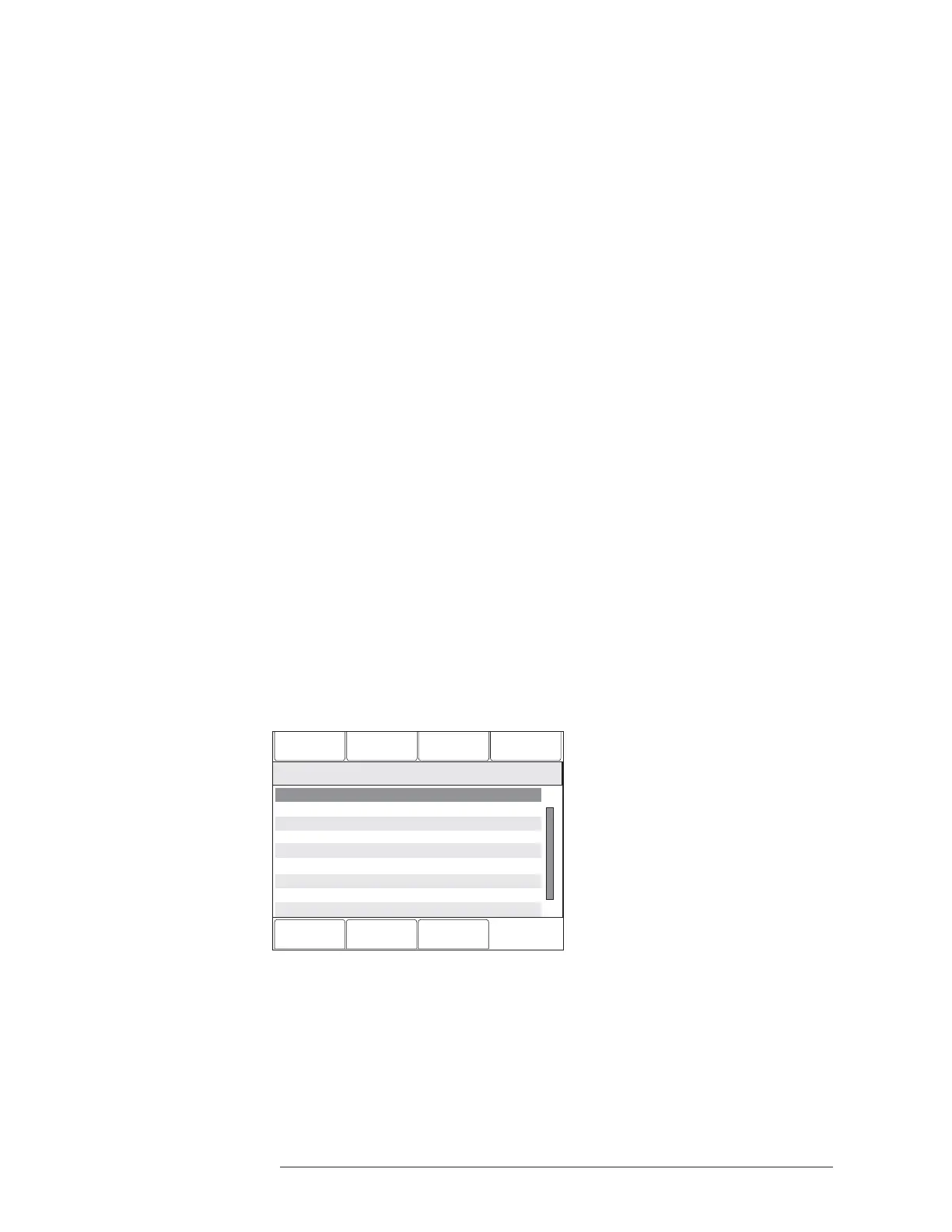
Changing Views To change from the Physical View to the Geographic View, press the Geographic View
soft key (when available). The soft key will then toggle to read Physical View. The
Physical/Geographic View Soft keys appear when the screen shows the tree struc-
ture of the system, as displayed in Figure 1-3.
Configuration
Status
Queue
10:53
Category text information
Cancel
Geographic View
GoTo
History
Menu:Report
PHY:FireFighter@1, DLC@1
10:53
Category text information
2 ZIC-4A “ZIC-4A at address 2”
3 “ at address 3”ZIC-4A ZIC-4A
4 NIC “Network Interface Card”
5 PSC-12 “Power Supply”
6 RPM “RPM at address 6”
253 PMI-C “Control Panel”
1 DLC “DLC at address 1”
Figure 1-3
Screen Displaying Tree Structure Of System In Physical View

 Loading...