CHAPTER 3 | FCM2041-U3 OPERATOR INTERFACE MANUAL
MAINTENANCE MODE
3-15
Activate/Deactivate To use the Activate/Deactivate feature, navigate to the desired device (Physical View) using
the More Info/+ or
(FCM2041-U3) buttons, select the Control option by pressing the
Control soft key and then “Touch” the box labeled Activate (or Deactivate). Note that this
feature is available at the Device level only and is not available in Geographic View.
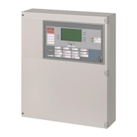
The Activate/Deactive Devices screen displays showing the location. See Figure 3-25.
In this example, AT: Cerberus PRO Modular@1, DLC@1, HFP11@2, where:
• FireFinder@1—Node 1 of the FireFinder System
• DLC@1—the DLC module at address 1
• HPF11@2—the HFP-11 detector at device address 2
Menu:Maint:Control:Acti vate
PHY: @1FireFinder , DLC@1, HFP11@2
Cancel Settings Execute
ACTIVATE INPUT
COMPONENT: Smoke/Photo
AT: Cerberus PRO Modular@1, DLC@1, HFP11@2
Figure 3-25
Maintenance: Control: Activate Inputs Screen
To select a component, press the Settings soft key.
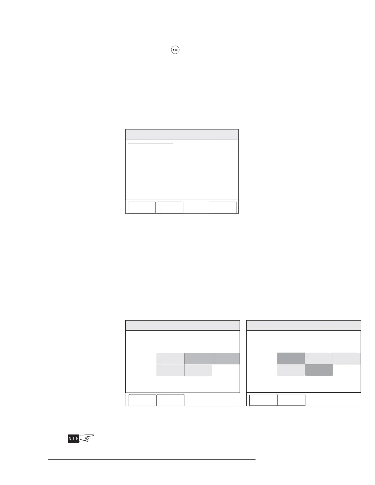
Inputs The components section of the screen displays the items that can be selected. See
Figure 3-26a and 3-26b. Items that can not be selected are grayed out based on the
device selected. (In Figure 3-26a, Switch 1 and Switch 2 are grayed out; in Figure
26b, Scan and Fire 2 are grayed out.) Make a selection of the component you wish to
activate, then press the OK soft key. Note that the Activate/Deactivate feature works
with DLC, XDLC, MLC and VPM (VESDA) devices. For MLC devices, only FP-11 and
MSI-2 series devices have multiple components that are selectable.
Maint:Control:Activate:Settings
FireFinder@1, DLC@1, HFP11@2
Components
Cancel OK
Switch 1
Neural
Smoke/Photo
Thermal
Switch 2
Figure 3-26a Figure 3-26b
Activate Input Settings - DLC, XLDC and MLC Activate Input Settings - VPM (VESDA)
At this point, the component that was selected is not yet activated.
Maint:Control:Activate:Settings
FireFinder@1, VPM@1, VLC@2
Components
Cancel OK
Alert
Fire 2
Scan
Fire 1
Action

 Loading...