28 / 94
Siemens RDF800KN.., RDF800KN/VB, RDD810KN/NF Basic documentation CE1P3174en
Smart Infrastructure 2020-02-21
3.4.1 Applications for fan coil systems (RDF800KN..,
RDF800KN/VB only)
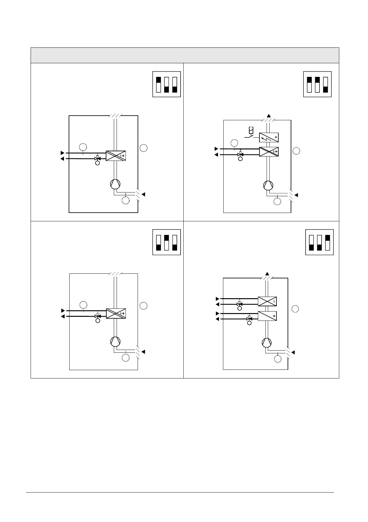
Application and output signal, DIP switches, diagram
· 2-pipe fan coil unit On/Off
(heating or cooling)
1
ON
2 3
· 2-pipe fan coil unit with electric
heater
(heating or cooling) On/Off
1
ON
2 3
3076D20
(B1)
M1
V1
T
B2
T
T
(B1)
V1
M1
3171D21
T
B2
E1
T
(B1)
T
(B1)
· 2-pipe fan coil unit 3-position
(heating or cooling)
1
ON
2 3
· 4-pipe fan coil unit On/Off
(heating and cooling)
1
ON
2 3
3076D20
(B1)
M1
V1
T
B2
T
T
(B1)
T
V2
V1
M1
307 6D22
(B1)
T
(B1)
V1 Heating or heating/cooling valve actuator B1 Return air temperature sensor or external room
temperature sensor (optional)
V2 Cooling valve actuator B2 Changeover sensor (optional)
E1 Electric heater M1 1- or 3- speed fan
 Loading...