84 / 94
Siemens RDF800KN.., RDF800KN/VB, RDD810KN/NF Basic documentation CE1P3174en
Smart Infrastructure 2020-02-21
6. Connection
6.1 Connection terminals
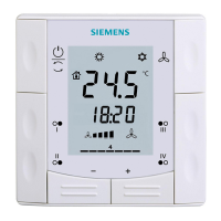
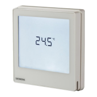
RDF800KN.., RDF800KN/VB
L X1 M
N
Q1 Q2 Q3
Y1
SELV
Y2
X2
CE+ CE
-
L, N Operating voltage AC 230 V
Q1 Control output "Fan speed 1 AC 230 V"
Q2 Control output "Fan speed 2 AC 230 V"
Q3 Control output "Fan speed 3 AC 230 V"
Y1,Y2 Control output "Valve" AC 230 V (NO, for normally closed
valves), output for compressor or electric heater
X1, X2 Multifunctional inputs for temperature sensor (e.g.
QAH11.1) or potential-free switch
Factory setting:
– X1 = window contact
– X2 = external sensor
(function can be selected via P38 or P40)
M Measuring neutral for sensor and switch
CE+ KNX data +
CE- KNX data -
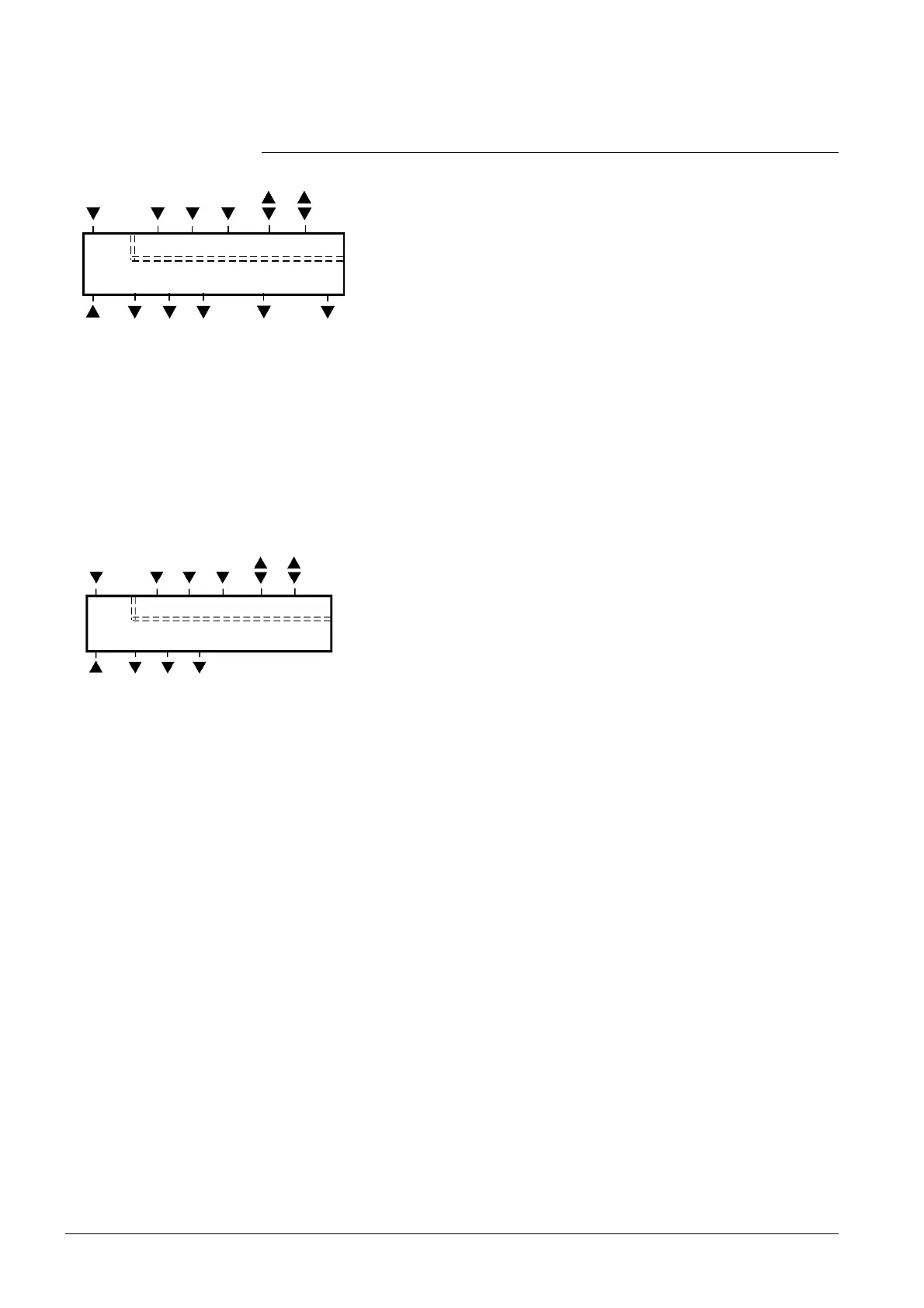
L X1 M
N
Q11 Q14 Q12
SELV
X2
CE+ CE
L, N Operating voltage AC 230 V
Q11, Q12 NC contact (for NO valves)
Q11, Q14 NO contact (for NC valves)
X1, X2 Multifunctional input for temperature sensor or potential-
free switch
Factory setting:
– X1 = window contact
– X2 = external sensor
(function can be selected via P38 or P40)
M Measuring neutral for sensor and switch
CE+ KNX data +
CE- KNX data -
 Loading...