41 / 94
Siemens RDF800KN.., RDF800KN/VB, RDD810KN/NF Basic documentation CE1P3174en
Smart Infrastructure 2020-02-21
3.6.5 4-pipe fan coil unit (RDF800KN.., RDF800KN/VB only)
On 4-pipe applications, the thermostat controls 2 valves in heating and cooling
mode, heating/cooling mode by manual selection (P01 = 2), or heating and cooling
mode with changeover. Heating and cooling mode (P01 = 4) is factory-set.
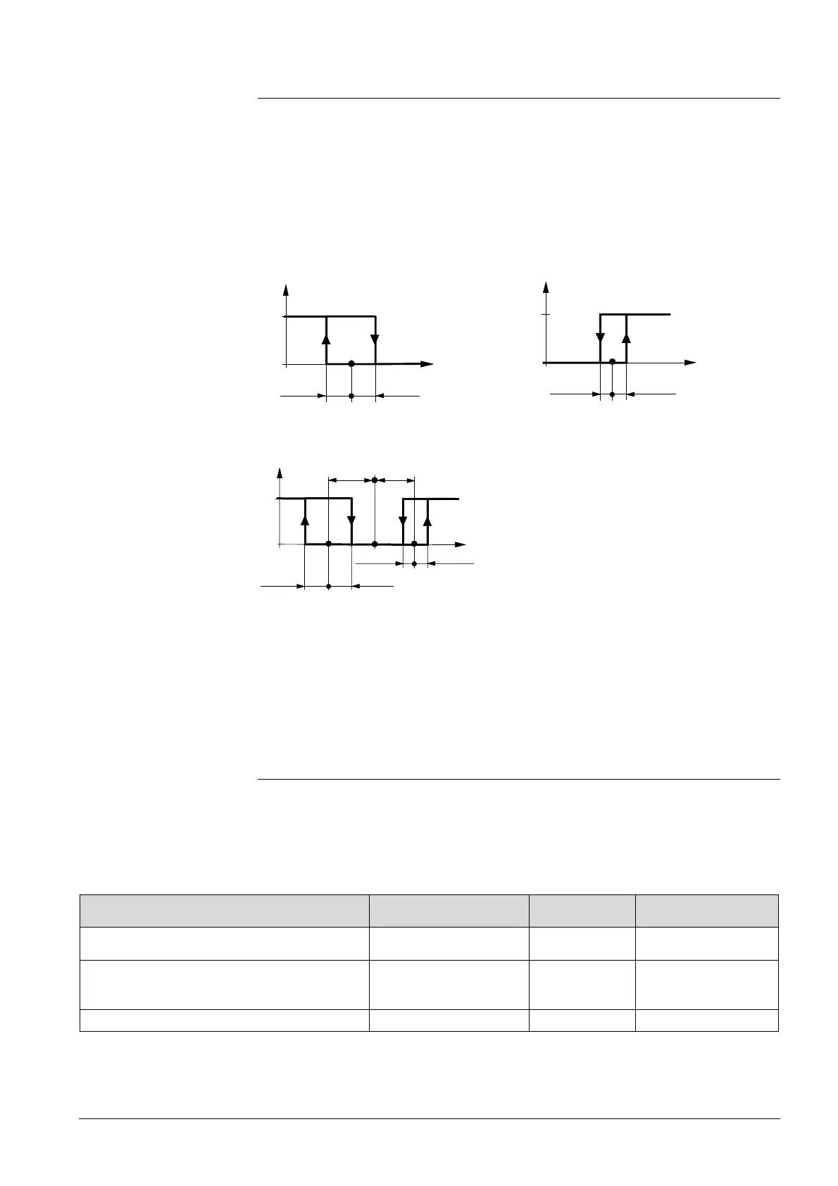
The diagrams below show the control sequence for 2-position control.
Heating mode with manual selection
(P01 = 2)
Cooling mode with manual selection
(P01 = 2)
½ SDC
0
½ SDC
w
T[°C]
V2
Heating and cooling mode (P01 = 04)
½ SDC
0
½ SDC
w
T[°C]
V2
½ SDH ½ SDH
V1
½x
dz
½x
dz
T[°C] Room temperature
w Room temperature setpoint
V1 Control command "Valve" or "Comp." (H)
V2 Control command "Valve" or "Comp." (C)
SDH Switching differential "Heating" (P30)
SDC Switching differential "Cooling" (P31)
X
dz
Dead zone (P33)
· The diagrams only show the PI thermostat’s proportional action.
· For the fan sequence see section 3.8.
Refer to sections 3.4, 3.6.1, and 3.7.
3.6.6 Chilled/heated ceiling and radiator applications
(RDF800KN.., RDF800KN/VB only)
For chilled/heated ceilings and radiators, proceed as follows:
1. Set the corresponding basic application;
2. Disable the fan (P52).
The following applications are available:
Application for
Set basic application See section Sequences
Chilled/heated ceiling with changeover
2-pipe 3.6.3
H (
)
C (
)
Chilled/heated ceiling and electric heater
(cooling only: disable electric heater using
P13)
2-pipe and electric
heater
3.6.4
El H + H ( 7\ \ )
El H + C ( 7\ / )
C (
)
Chilled ceiling and radiator
4-pipe 3.6.5
H + C ( \ / )
Setting the sequence
½ SDH
1
0
½ SDH
V1
 Loading...