67 / 94
Siemens RDF800KN.., RDF800KN/VB, RDD810KN/NF Basic documentation CE1P3174en
Smart Infrastructure 2020-02-21
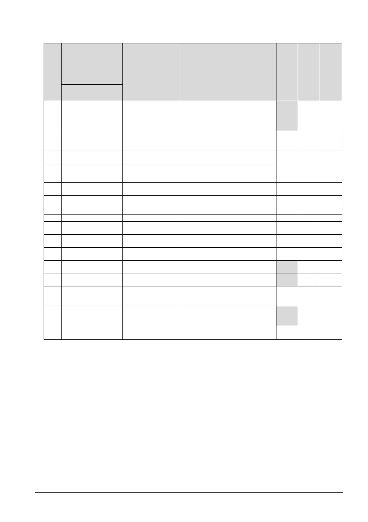
3.14.3 Service level parameters
Parameter
Name Factory setting Range
RDD810KN/NF
RDF800KN..,
RDF800KN/VB
Dependencies
Service level
P01 Control sequence
2-pipe:
1 = cooling only
4-pipe:
4 = heating and cooling
0 = heating only
1 = cooling only
2 = H/C changeover manual
3 = H/C changeover auto
4 = heating and cooling
x
ü
P02
Operation using room op
selector
1 1 = Auto – Protection
2 = Auto - Comfort - Economy –
Protection
ü ü
P04 Unit 0
0 = °C
1 = °F
ü ü
P05
Measured value
correction (for built-
in/external sensor)
0 K – 3...3 K
ü ü
P06 Standard display 0
0 = room temperature
1 = setpoint
ü ü
P07
Additional display
information
0
0 = --- (no display)
3 = time of day (12 hour) (using bus)
4 = time of day (24 hours) (using bus)
ü ü
P08 Comfort basic setpoint 21 °C 5...40 °C
ü ü
P09
Comfort setpoint
minimum
5 °C
5...40 °C
ü ü
P10
Comfort setpoint
maximum
35 °C
5...40 °C
ü ü
P11 Economy heating setpoint 15 °C
OFF, 5...WCoolEco;
WCoolEco = 40 °C max.
ü ü
P12 Economy cooling setpoint 30 °C
OFF, WHeatEco...40 °C;
WHeatEco = 5 °C min.
x
ü
P13
Electric heater when
cooling
ON
ON: Enabled
OFF: Disabled
x
ü
Appl.
*)
P14 "Screen lock" function 0 0: Unlock
1: Lock
2: Setpoint adjustable
ü ü
P15
Fan stage in dead zone
(Comfort)
0 0 = disabled
1 = low speed (Heat and Cool)
2 = low speed (Cooling only)
x
ü
P16 Buzzer function 1 0: disabled
1: enabled
ü ü
*)
Appl. = applications
Parameter display depends on the selected application and function.
 Loading...