Connecting
5.2 Ports
SCALANCE X-400
104 Operating Instructions, 06/2015, C79000-G8976-C186-12
Connectors of the digital inputs of the SCALANCE X414-3E
Polarity reversal protection X1, X2
The two 5-pin male connectors (X1, X2) of the digital inputs 1 through 8 have no polarity
reversal protection. If the connectors are accidentally swapped over, this does not cause
damage or destroy circuits. In display modes A and C or B and D, incorrect inputs are
displayed during the time the connectors are swapped over.
The input voltage must not exceed + 30 V and must not fall below – 30 V, otherwise the DI
module will be destroyed.
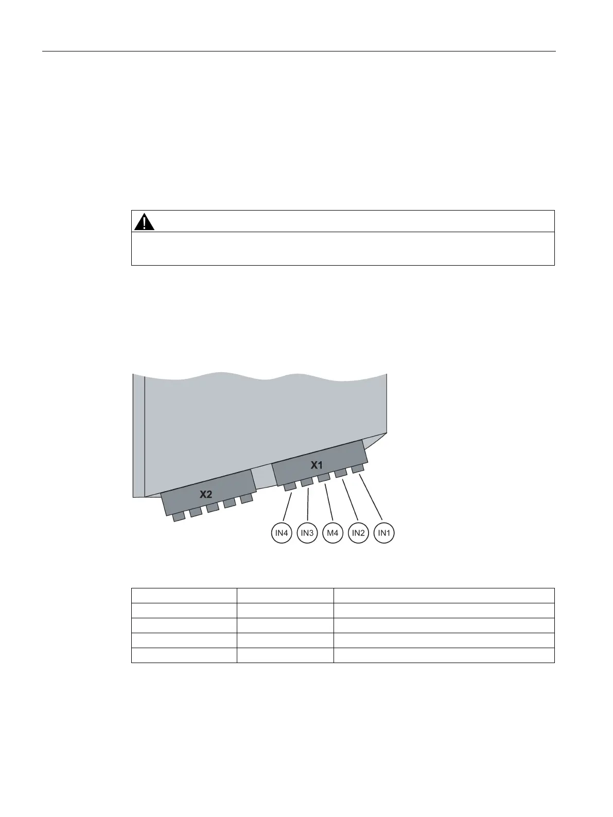
Connectors of the digital inputs 1 to 4 on male connector X1
Digital inputs 1 through 4 are connected using a 5-pin connector at the front terminal block
on the DI module.
Figure 5-3 Pins of connector X1 (inputs 1-4)
 Loading...