Configuration / project engineering
6.5 LED display
SCALANCE X-400
126 Operating Instructions, 06/2015, C79000-G8976-C186-12
LED display - CPU module
CPU module
On the SCALANCE X414-3E, the LEDs of the CPU module are on slot 4;
on the SCALANCE X408-2, they are on slot 3.
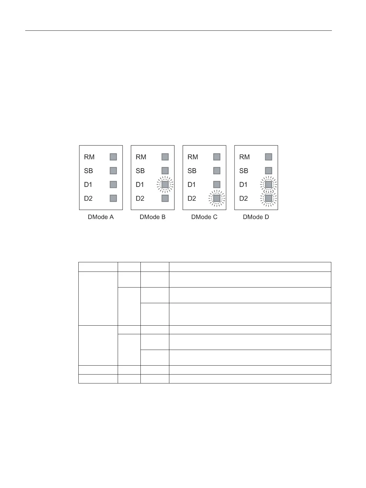
Display modes A through D
The set display modes are indicated as follows:
Figure 6-8 Display of the possible display modes (DMode A through DMode D)
The individual functions (RM, SB and D1/D2) are independent of each other. The LED
displays are described below:
RM off The IE Switch X-400 is not operating in redundancy manager
Green on The IE Switch X-
400 is operating in redundancy manager mode.
The ring is working without problems, monitoring is activated.
flashes The IE Switch X-
400 is operating in redundancy manager mode.
An interruption has been detected on the ring; the IE Switch -
400 has switched through.
SB
The standby function is disabled.
Green on The standby function is enabled and the standby ports are disa-
flashes The standby function is enabled and the standby ports are ena-
bled; in other words, the send and receive frames.
 Loading...