Description
3.4 Description of the product
SCALANCE X-400
48 Operating Instructions, 06/2015, C79000-G8976-C186-12
The following can be signaled over a floating signaling contact:
● Power failure.
The power supply monitored (L1/L2) is selected in the fault mask.
● Bad link status of a port.
(Bad connector or no connection to partner device). The port monitored is selected in the
fault mask.
If the SCALANCE X408-2 is set as the redundancy manager, the following errors are also
reported:
● Bad link status of the ring ports, regardless of the status of the fault mask.
● A second IE Switch X-400 is configured as redundancy manager in the same ring.
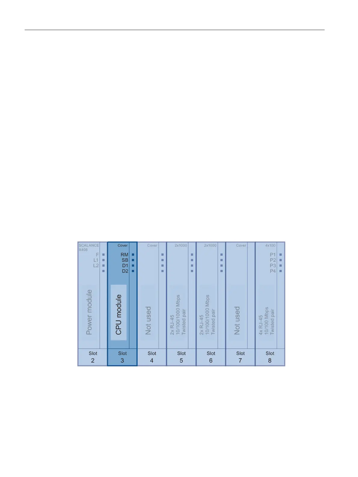
SCALANCE X408-2 switch functionality
CPU module
Slot 3 symbolizes the CPU module.
This module has four LEDs for displaying parameter assignments that can be modified by
the user with software and a SELECT/SET button.
Figure 3-21 LEDs on slot 3
The SCALANCE X408-2 has an RS-232 port. This is located on slot 8.
 Loading...