Description
3.4 Description of the product
SCALANCE X-400
Operating Instructions, 06/2015, C79000-G8976-C186-12
47
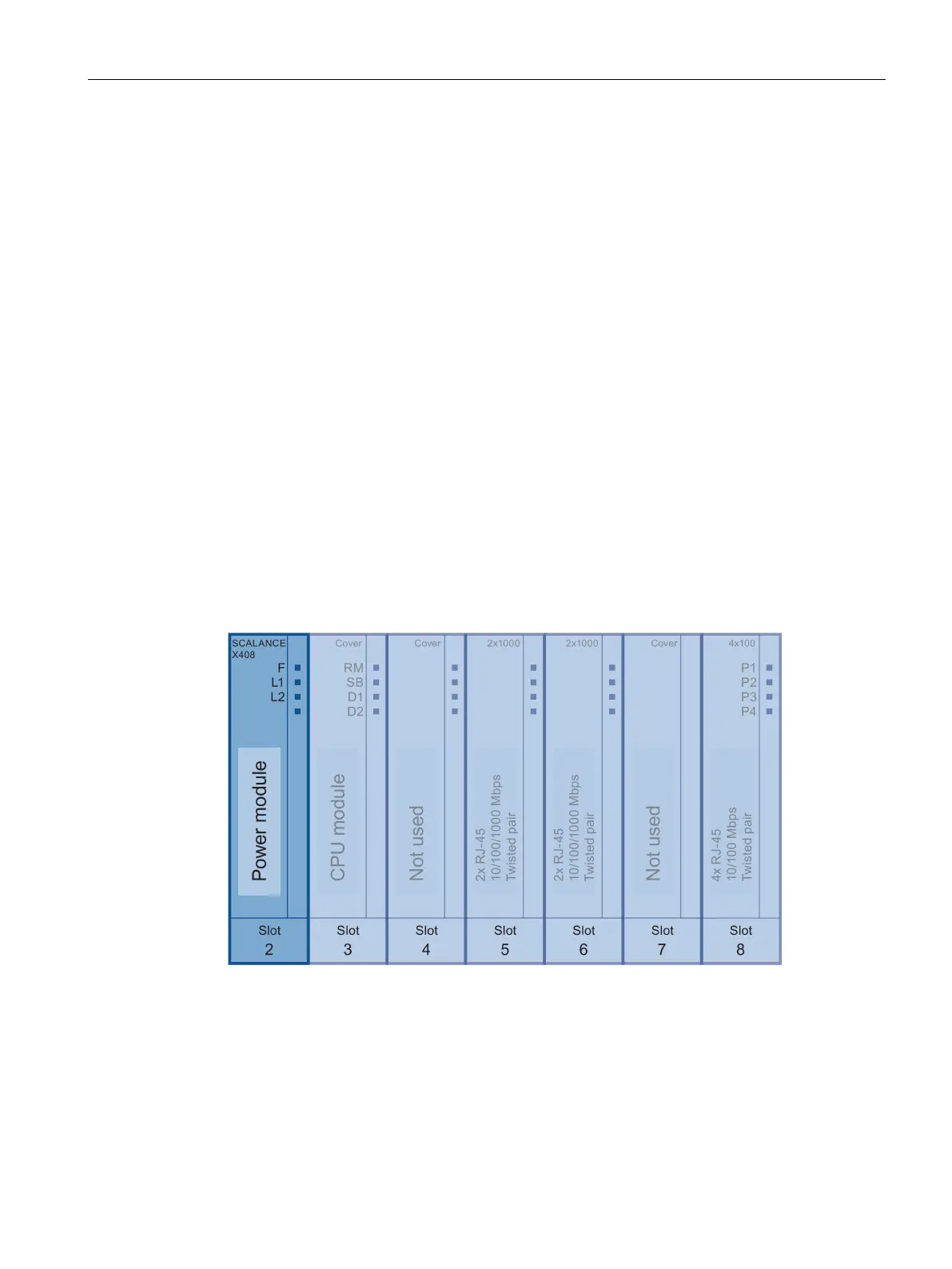
● Slot 7
No function in system.
● Slot 8
– Contains four RJ-45 jacks allowing attachment of 4 electrical (twisted pair)
connections (10, 100 Mbps). These cannot be used by media modules.
It also includes one D-sub socket.
– A serial RS-323 port for firmware update or management over the Command Line
Interface (CLI).
SCALANCE X408-2 power module
Introduction
The power module is located in slot 2.
The power module can be supplied with power redundantly over two inputs.
The two power inputs are isolated from each other, there is no power distribution.
If redundant power feed-in is used, the switch is supplied solely by
the section of the power module with the higher output voltage.
The front 4-pin connector is used for the power supply. The input voltage is 24 V DC (20.4 –
28.8 V). The signaling contact supplies the fault status at the rear 4-pin connector. If there is
a fault, the contact opens.
Figure 3-20 Slot of the power module
 Loading...