Description
3.2 Network topologies
SCALANCE X-400
Operating Instructions, 06/2015, C79000-G8976-C186-12
17
Star/tree structure
Functional description
Star/tree structures can be created with IE Switches X-400. The cascading depth and total
span of a network are limited only by the signal propagation times of the communication
connections.
Properties of a star structure
Each IE Switch X-400 communicates over a TP or FO cable with a central switch with which
all other switches are also connected within a star structure. Communication is possible over
the optical or the electrical ports.
For more detailed information, refer to the table below.
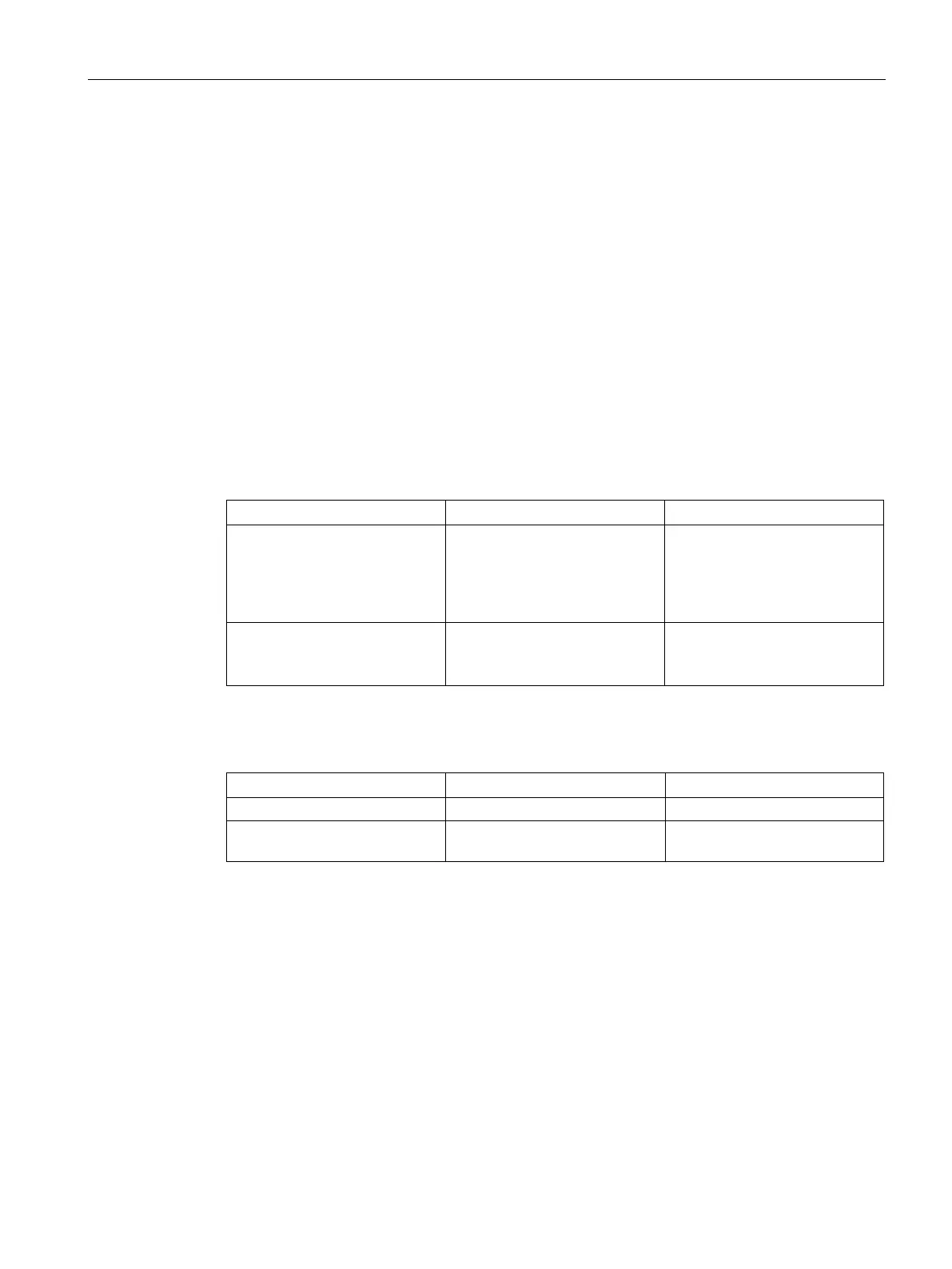
Table 3- 3 Optical ports (on the slots)
Gigabit
MM492-2, MM492-2LD,
MM492-2LH,
MM492-2LH+ or
5
5 and 6
Fast Ethernet
MM491-2, MM491-2LD or
6 and 7
with extender: 12, 13, 14 and 15
5 and 6
Table 3- 4 Electrical ports (on the slots)
Fast Ethernet 5 and 9 through 11
(12 and 13 with extender)
5, 6 and 8
With the fault mask, it is possible to monitor the port states using the signaling contact. In
addition to connecting the switches to the central IE Switch X-400, it is also possible to
connect one or more end devices.
 Loading...