12-2
Operator Panel OP3
Edition 11/99
12.1 Connecting to an S7-200 via the PPI
When you are connecting an OP3 to an S7-200, connect the OP3 to the
S7-200’s PPI interface. In this particular instance, up to two S7-200s can be
connected to the OP3.
Similarly, you can connect several OP3s to a S7-200. In this particular case,
only one connection is possible at any one time from the point of view of the
S7-200. The S7-200 can communicate with an OP3 and a PU in the same
manner, the PU likewise being the master.
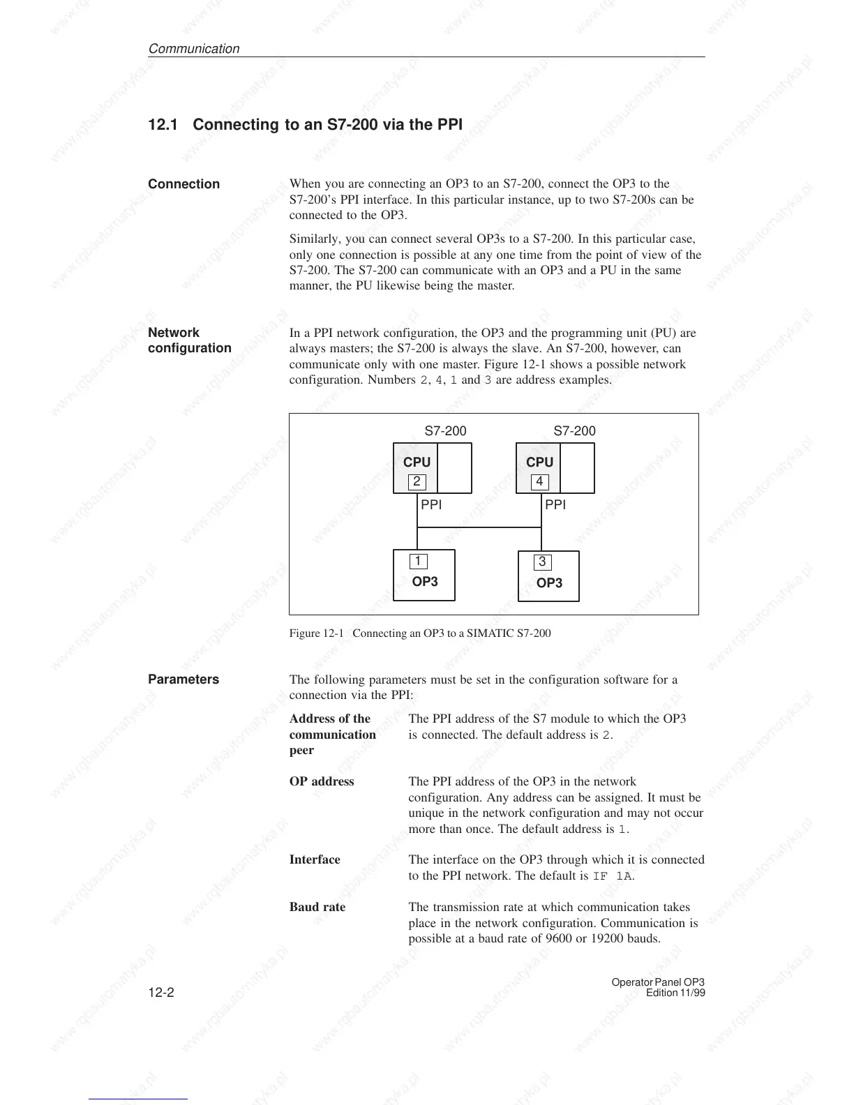
In a PPI network configuration, the OP3 and the programming unit (PU) are
always masters; the S7-200 is always the slave. An S7-200, however, can
communicate only with one master. Figure 12-1 shows a possible network
configuration. Numbers 2, 4, 1 and 3 are address examples.
CPU
2
CPU
4
PPI
OP3
1
PPI
S7-200 S7-200
OP3
3
Figure 12-1 Connecting an OP3 to a SIMATIC S7-200
The following parameters must be set in the configuration software for a
connection via the PPI:
Address of the The PPI address of the S7 module to which the OP3
communication is connected. The default address is 2.
peer
OP address The PPI address of the OP3 in the network
configuration. Any address can be assigned. It must be
unique in the network configuration and may not occur
more than once. The default address is 1.
Interface The interface on the OP3 through which it is connected
to the PPI network. The default is IF 1A.
Baud rate The transmission rate at which communication takes
place in the network configuration. Communication is
possible at a baud rate of 9600 or 19200 bauds.
Connection
Network
configuration
Parameters
Communication

 Loading...