12-5
Operator Panel OP3
Edition 11/99
12.3 Interface Area for the SIMATIC S7
The interface area is required only if it is intended that the following
functions be used or evaluated by the SIMATIC S7:
• Sychronize the date and time of the S7 and the OP3
• Evaluate the connection ID and
• Detect OP3 start-up in the S7 program.
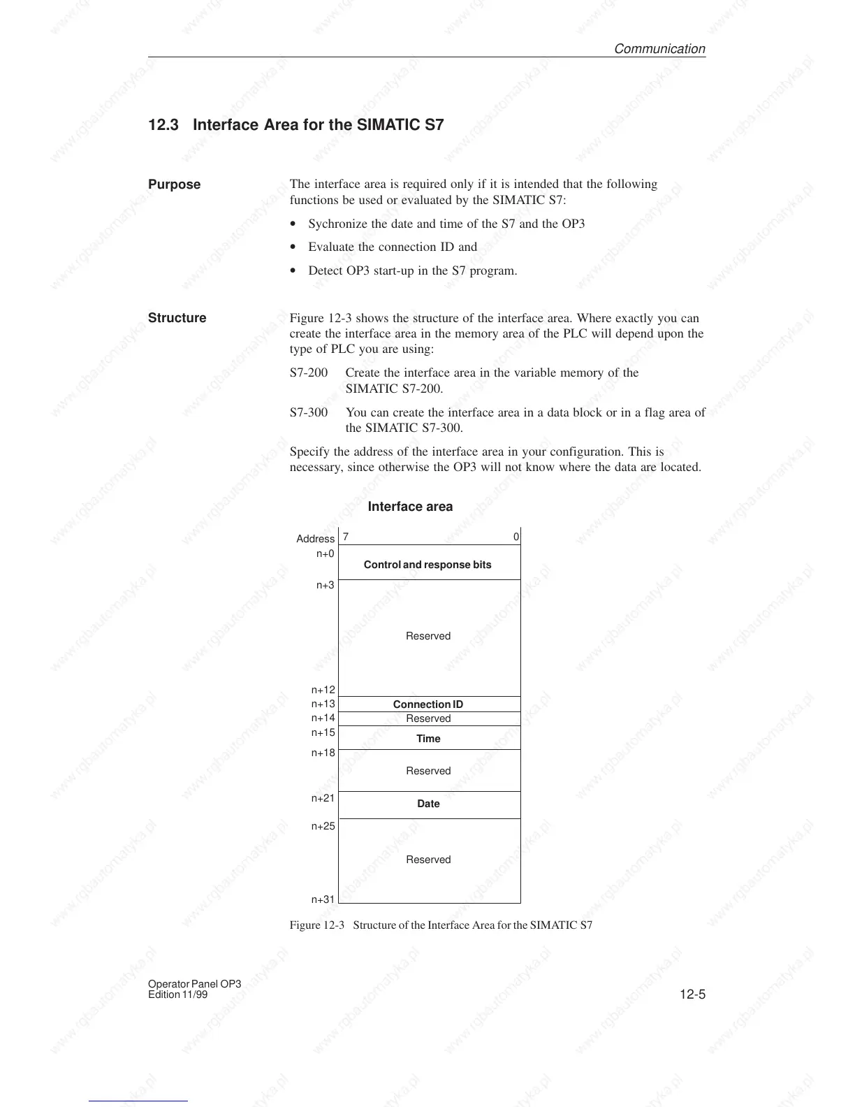
Figure 12-3 shows the structure of the interface area. Where exactly you can
create the interface area in the memory area of the PLC will depend upon the
type of PLC you are using:
S7-200 Create the interface area in the variable memory of the
SIMATIC S7-200.
S7-300 You can create the interface area in a data block or in a flag area of
the SIMATIC S7-300.
Specify the address of the interface area in your configuration. This is
necessary, since otherwise the OP3 will not know where the data are located.
70
Address
Control and response bits
Interface area
n+0
n+3
n+12
n+14
n+25
Connection ID
Time
Date
n+13
n+18
n+15
n+21
Reserved
Reserved
Reserved
Reserved
n+31
Figure 12-3 Structure of the Interface Area for the SIMATIC S7
Purpose
Structure
Communication

 Loading...