*HWWLQJ6WDUWHG
Getting Started - ET 200S-IM 151/CPU Interface Module
A5E00058783-01
8-4
6WHS:LULQJWKH(76,0&38DQG6
6WDJH 'HVFULSWLRQ
1 Wire the S7-300 as described in the
S7-300 Programmable Controller, Hardware and
Installation
manual or in
STEP 7 Getting Started, V5.0
.
2 Extend the connections of the 4 switches using a cable. Strip 6 mm off the cable ends and
attach wire end ferrules.
3 Connect the inputs 1.1 (terminal 13) and 1.2 (terminal 14) on the DI of S7-300 by means of a
switch to L+ on the PS of the S7-300.
4 Connect the two remaining 1-pin switches to the DI of the ET 200S as follows:
• One switch to terminals 1 and 3
• The other switch to terminals 5 and 7
$QRWHRQVSULQJWHUPLQDOV
To release the spring in a connection, insert a screwdriver with a 3 mm blade into the upper
round hole in the terminal until it reaches the stop, moving the screwdriver upwards slightly, if
necessary. You can then insert a free cable end into the square hole below. Remove the
screwdriver and check that the cable is in position securely.
5 Wire terminal 2 of the TM of the PM to L+ of the PS and terminal 3 of the TM of the PM to M of
the PS. Strip 11 mm from the cable ends, and attach wire end ferrules.
6 Wire terminal 1L+ of the IM 151/CPU to L+ of the PS and terminal 1M of the IM 151/CPU to M
of the PS.
1RWH
• Strip 11 mm from the cable ends that have to be connected, and attach wire end ferrules.
• You can also use the power supply of the S7-300 for the IM 151/CPU and the PM.
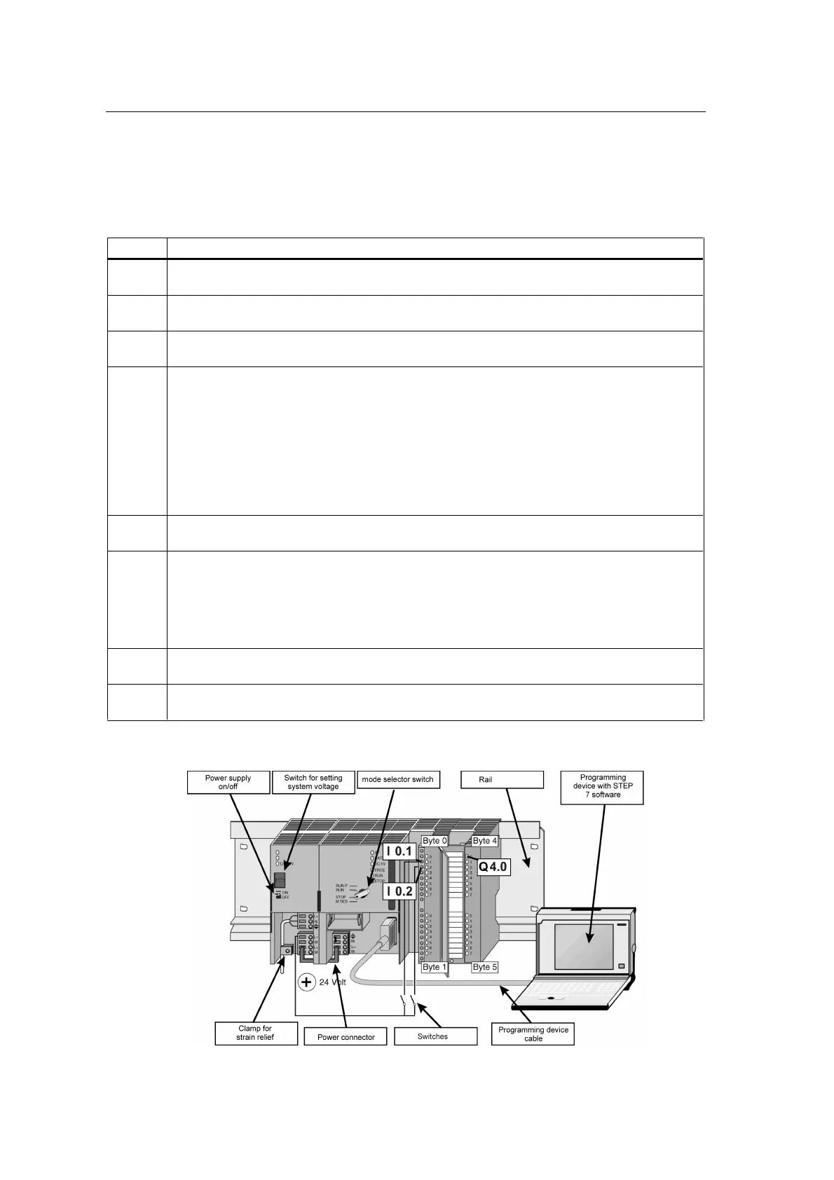
7 Connect the programming device and the IM 151/CPU to the programming device cable, and
secure all the connectors.
8 Connect the PS of the ET 200S, the PS of the S7-300 and the programming device to the
network.
9LHZRIWKH6(the wiring of the power supply of the DI and the DO is not
shown; the programming device is connected to the S7-300)

 Loading...