Commissioning and Diagnostics
4-11
ET 200S Interface Module IM 151/CPU
A5E00058783-01
4.5 Diagnostics via Diagnostic Address with
STEP 7
Malfunctions that occur in the ET 200S are indicated by the “SF” LED, and the
cause is entered in the diagnostic buffer of the IM 151/CPU. Either the CPU
component of the IM 151/CPU goes into STOP mode, or you can respond to errors
by means of error or interrupt OBs in the user program.
To enable a response to be made, it must be possible to identify whatever caused
the problem by means of a diagnostic address.
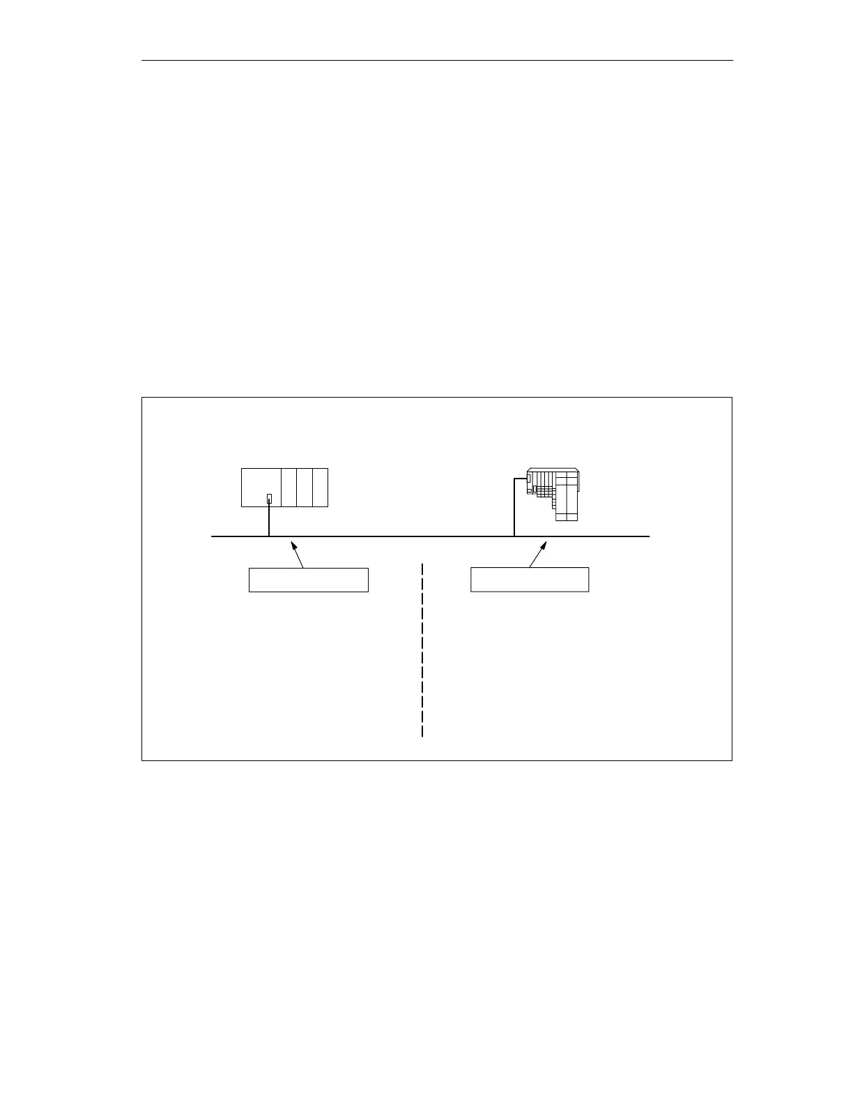
Diagnostic Addresses
If you run the ET 200S with a DP master from the SIMATIC S7 range on the
PROFIBUS-DP, diagnostic addresses are assigned in
STEP 7
as follows:
You specify two diagnostic addresses during configuration:
PROFIBUS
ET 200S
DP Master (SIMATIC S7)
Diagnostic address
Diagnostic address
When configuring the DP master, you specify
(in the associated project for the DP master)
a diagnostic address for the ET 200S.
During configuration of the ET 200S,
STEP 7
sets the diagnostic address 1534 by default for
the ET 200S (in the associated project for the
ET 200S).
The DP master receives information on the
status of the ET 200S or on a bus
interruption by means of this diagnostic
address.
The ET 200S receives information on the status of
the DP master or on a bus interruption by means of
this diagnostic address.
Figure 4-2 Diagnostic Addresses for the DP Master and ET 200S

 Loading...