Configuration Frame and Parameter Assignment Frame for the ET 200S
A-3
ET 200S Interface Module IM 151/CPU
A5E00058783-01
Identifiers for the Address Areas
The identifiers for configuration depend on the type of the address area. The
following table lists all the identifiers for the address areas.
Table A-2 Identifiers for the Address Areas of the Intermediate Memory
Identifiers (Hexadecimal)
Address Area
SFF Length Byte Manufacturer-Specific Data
Comment Length = 3
Byte 0 Byte 1 Byte 2 Byte 3 Byte 4
Input See Figure A-1 See Figure A-2 00
H
83
H
40
H
Output 00
H
93
H
40
H
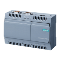
Byte 0
70
Bit no.
6
4
5
312
0011: Number of manufacturer-specific
data items (bytes 2, 3 and 4 in Table A-2)
00
00: Spacesaver
01: 1-byte length byte for input data follows
10: 1-byte length byte for output data follows
Figure A-1 Description of Byte 0 of the Address Area Identifiers
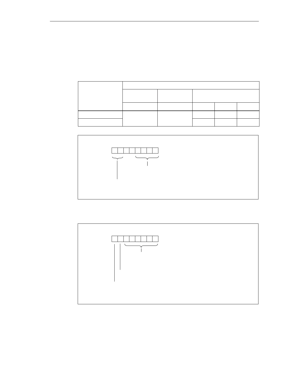
Byte 1
70
Bit no.
6
4
5
312
Length of the input/output data in bytes or words +1
0: length in bytes
1: length in words
Consistency over...
0: bytes or words
1: entire length
0: 1 byte/word
1: 2 bytes/words
Figure A-2 Description of Byte 1 of the Address Area Identifiers

 Loading...