Configuration Frame and Parameter Assignment Frame for the ET 200S
A-4
ET 200S Interface Module IM 151/CPU
A5E00058783-01
A.2 Structure of the Configuration Frame (AKF)
DDB (Device Database) File
If your DP master doesn’t support the configuration frame in the special ID format
(e.g. a non-SIMATIC DP master), you can obtain a DDB file with the normal ID
format on the Internet at http://www.ad.siemens.de/csi/gsd (see also Section 5.1).
Structure of the Configuration Frame
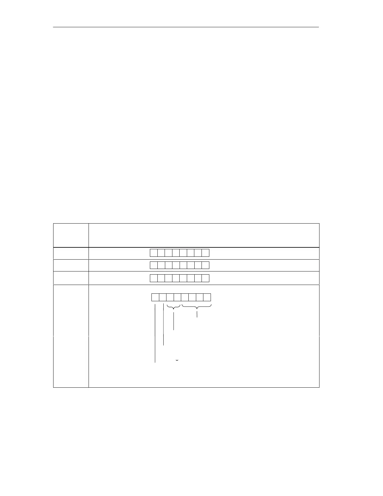
The length of the configuration frame depends on the number of configured
address areas of the intermediate memory of the CPU component. The first three
bytes of the configuration frame are always “0”. This represents the 3 fixed 1-byte
identifiers. Maximum area that can be displayed: 0-16 bytes/words of inputs, 0-16
bytes/words of outputs, an asymmetrical configuration is possible.
The structure of the configuration frame in the normal identifier format is as follows:
Table A-3 Structure of the Configuration Frame in the Normal Identifier Format (AKF)
Configured
Address
Areas
Byte
1.
0000000
0
2.
0000000
0
3.
0000000
0
4.
70
Bit no.
6
4
5
312
:
Length of the input/output data in bytes or words
+1
p
:
0: length in bytes
1: length in words
:
npu
a
a
10: output data
32nd
Consistency over...
0: bytes or words
1: entire length

 Loading...