Addressing
2-2
ET 200S Interface Module IM 151/CPU
A5E00058783-01
2.1 Slot-Oriented Addressing
Slot-Oriented Address Allocation
In slot-oriented addressing (default addressing) each slot number in a module is
allocated an address area in the IM 151/CPU.
Depending on the type of the I/O module, the addresses are digital or analog (see
Table 2-1). The address allocation is not fixed and can be changed, but there is a
default address area.
0
127
128
255
256
1279
1280
1535
1 byte per digital module
or motor starter
DP range
16 bytes per analog module
Direct Communication
Figure 2-1 Structure of the Default Address Area
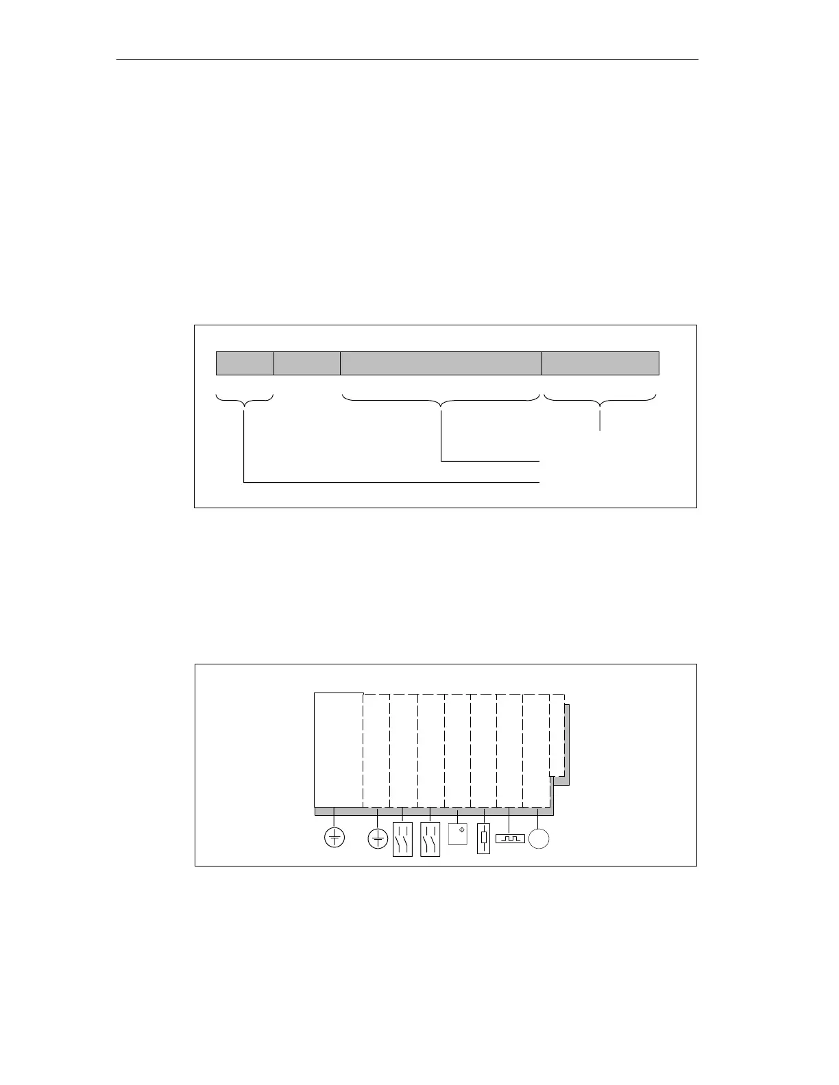
Slot Assignment
The figure below shows an ET 200S configuration with digital electronic modules,
analog electronic modules, process-related modules and the slot assignment.
Interface module
PM-E power module
2DI 24 V DC
2DI 24 V DC
2AO U
2AI RTD
1Count 24V/100kHz
1SSI
Term. element
SSI
456 10879
Slot
Figure 2-2 Slots on the ET 200S

 Loading...