Commissioning and Diagnostics
4-20
ET 200S Interface Module IM 151/CPU
A5E00058783-01
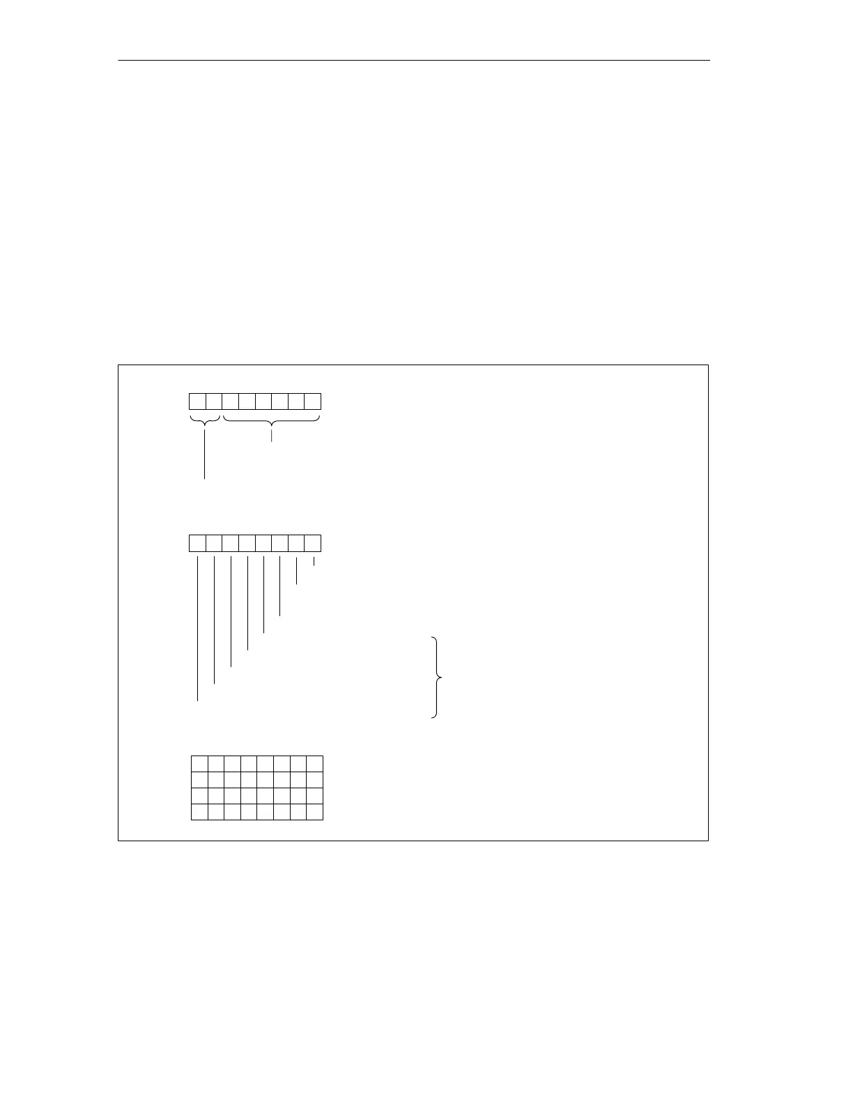
4.6.4 Module Diagnosis
Definition
The module diagnosis indicates for which of the configured address areas of the
intermediate memory an entry has been made. The figure below shows the
structure of the module diagnosis.
Structure
The figure below shows the structure of the module diagnosis.
Byte 6
70
Bit no.
Length of the module diagnosis, including byte 6
(up to 6 bytes, depending on the number of configured address areas)
Byte 7
1: Target actual configuration or CPU component of the IM in STOP
0: Target actual configuration or CPU component of the IM in RUN
Code for module diagnosis
01
7654 13
1st configured address area
Bit no.
Target configurationactual configuration
Target configurationactual configuration
2nd configured address area
3rd configured address area
4th configured address area
5th configured address area
20
Bit no.
Byte 8
713654
20
Byte 9
Byte 10
Byte 11
6th to 13th configured address area
14th to 21st configured address area
22nd to 29th configured address area
30th to 32nd configured address area
16 15
13
14
1112 10 9
181920
23 22
21 17
28 242729
303132
26 25
Events in the correspondingly configured
address areas are indicated by set bits.
76
8
Figure 4-4 Structure of the Module Diagnosis

 Loading...