Addressing
2-8
ET 200S Interface Module IM 151/CPU
A5E00058783-01
Rules for Address Allocation
You must comply with the following rules when allocating addresses for the
ET 200S with the IM 151/CPU:
Assignment of the address areas:
– Input data for the ET 200S is always output data for the DP master
– Output data for the ET 200S is always input data for the DP master
You access the data in the user program using load/transfer instructions or
SFCs 14 and 15.
The length, unit and consistency of the associated address areas for the DP
master and the DP slave must be identical.
Addresses for the master and the slave can be different in the logically identical
intermediate memory (mutually independent logical I/O address areas in the
master and the slave CPU)
When the IM 151/CPU is configured with
STEP 7
for operation in the S5 or in
non-Siemens systems, it is clear that only the logical addresses within the slave
CPU are allocated. The addresses are then assigned in the master system using
the specific configuration tool of the master system.
Addressing Interface in
STEP 7
The following table illustrates the principles of address allocation. You will also find
this table in the
STEP 7
interface. You must set the mode ”MS” (for master slave)
or ”DX” (direct connection) in
STEP 7
(see Section 3.5).
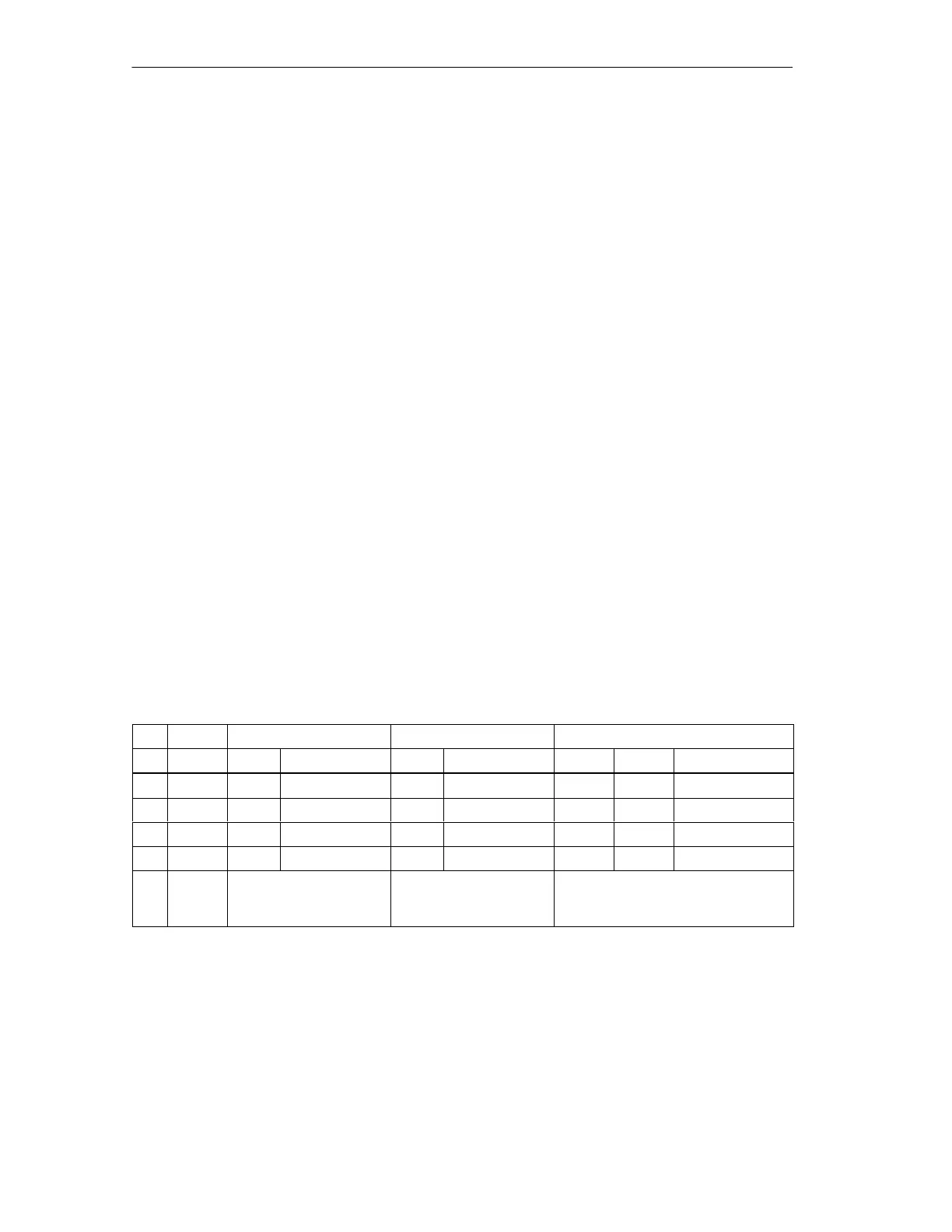
Table 2-4 Addressing Interface in
STEP 7 V5.1 (Extract)
Mode Master PROFIBUS-DP Partner Parameters
I/O Address I/O Address Length Unit Consistency
1 MS Q 200 I 128 4 Byte Unit
2 MS Q 300 I 132 8 Byte Total length
3 MS I 700 Q 128 4 Word Unit
4 MS I 50 Q 136 4 Byte Unit
MS:
Master
slave
Address areas in the
IM 151/CPU
Address areas in the
DP master CPU
These address area parameters
must be identical for the DP master
and the IM 151/CPU

 Loading...