Addressing
2-6
ET 200S Interface Module IM 151/CPU
A5E00058783-01
Address Areas for User Data Transfer with the DP Master
The ET 200S provides the PROFIBUS-DP with a maximum of 64 bytes of input
data and 64 bytes of output data. This data can be addressed in the intermediate
memory of the IM 151/CPU in up to 32 address areas.
An address area contains a maximum of 32 bytes. A maximum of 64 bytes is
available for input and output data.
The address areas start at 128 by default. The data is entered without a gap as of
address 128.
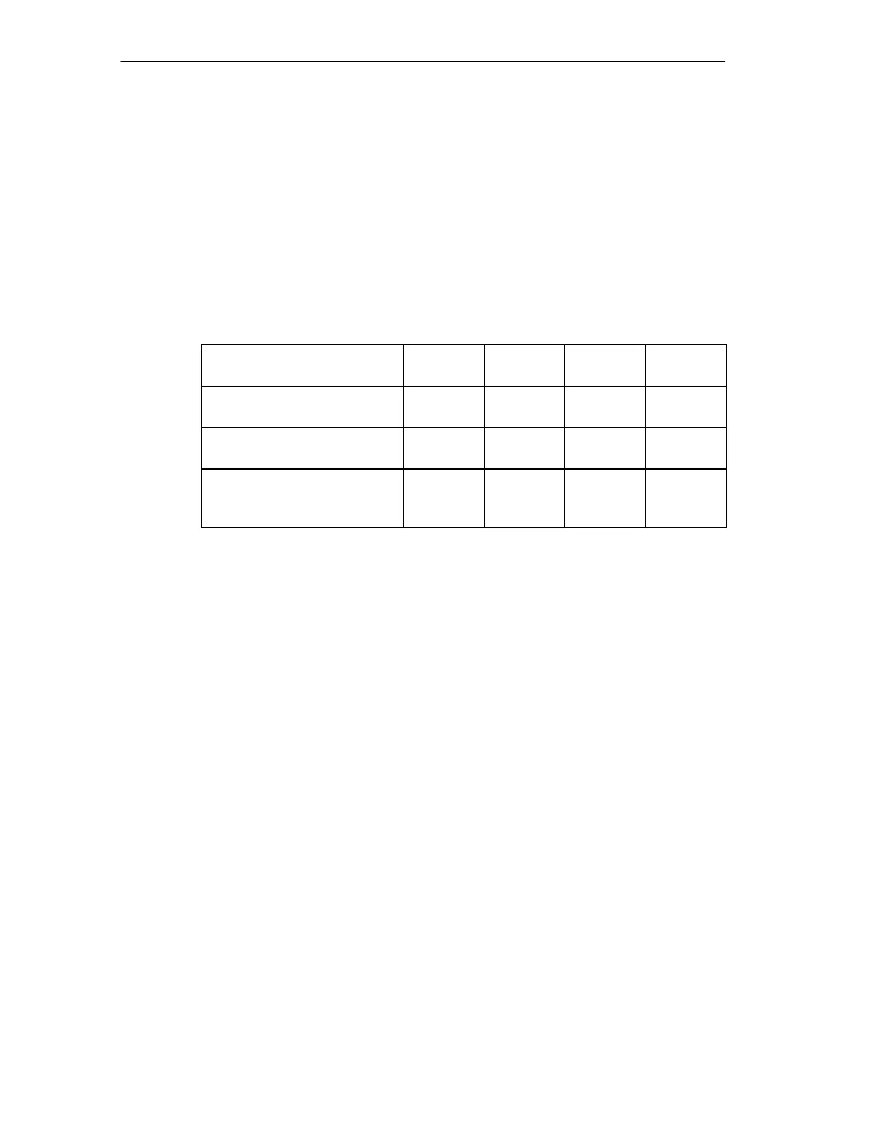
Table 2-2 Examples of the Maximum Configuration
Example
1
Example
2
Example
3
Example
4
Input address areas
Bytes per address area
16
4
2
32
16
4
0
0
Output address areas
Bytes per address area
16
4
2
32
16
2
32
2
Total no. of address areas
Total no. of bytes for inputs
Total no. of bytes for outputs
32
64
64
4
64
64
32
64
32
32
0
64
Data consistency
You define data consistency as byte, word, or overall consistency per address
area. Consistency can amount to up to 32 bytes/16 words per address area.
DP Diagnostic Address in
STEP 7
When the ET 200S is configured with
STEP 7
, a diagnostic address is set. The
ET 200S receives information on the status of the DP master or on a bus
interruption by means of this diagnostic address (see Section 4.5). In DP slave
operation the default diagnostic address is 1534.

 Loading...