Commissioning and Diagnostics
4-23
ET 200S Interface Module IM 151/CPU
A5E00058783-01
Additional Interrupt Information and Diagnostic Data
The meaning of the bytes as of byte (y+5) depends on byte (y+2):
Table 4-12 Additional Interrupt Information and Diagnostic Data
Byte (y+2) Contains the Code for...
Diagnostic Interrupt (01
H
) Process Interrupt (02
H
)
The diagnostic data contains the 16 bytes of
status information of the CPU component of
the IM 151/CPU. Figure 4-7 shows the
contents of the first four bytes of the
diagnostic data. The next 12 bytes are always
0.
For the process interrupt, you can program
four bytes of interrupt information. You
transfer these 4 bytes to the DP master in
STEP 7
using SFC 7 (“DP_PRAL”) (see
Section 4.5).
Diagnostic Data
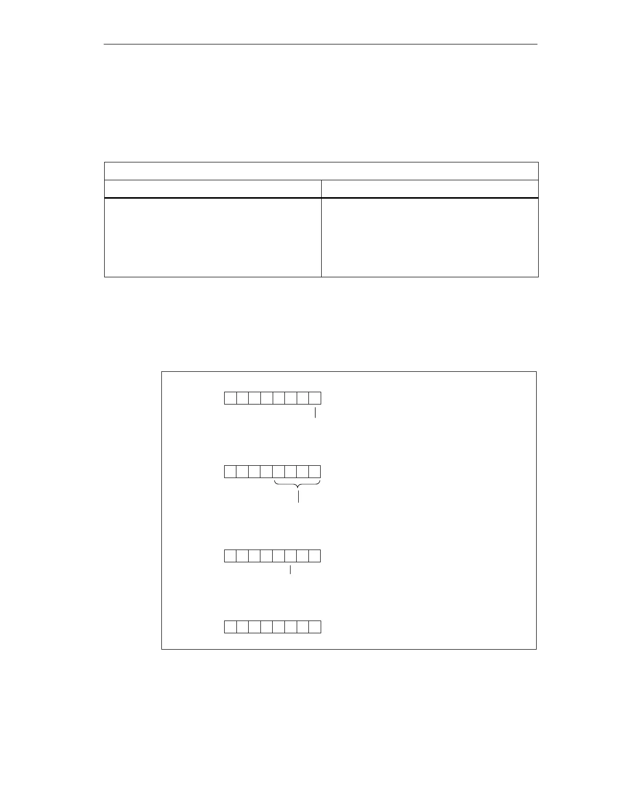
The figure below shows the structure and contents of the bytes for the diagnostic
interrupt. Bytes (y+8) to (y+20) are set to “0”.
Byte (y+5)
70
Bit no.
Byte (y+6)
Byte (y+7)
0: RUN mode
1: STOP mode
0: IM 151/CPU ok.
1: IM 151/CPU faulty
0
1
000 0
1
74 0
2
3 Bit no.
Bit no.
0
7
0
0
00000
1
Identifier for the address area of the
intermediate memory (constant)
0000000
Bytes (y+8)
to (y+20)
70
Bit no.
00000000
Figure 4-7 Structure of the Station Diagnosis (2)

 Loading...