Configuration Frame and Parameter Assignment Frame for the ET 200S
A-2
ET 200S Interface Module IM 151/CPU
A5E00058783-01
A.1 Structure of the Configuration Frame (SKF)
The length of the configuration frame depends on the number of address areas
configured in the intermediate memory of the CPU component. The first 15 bytes
in the configuration frame are already allocated because the first 3 identifiers of the
5-byte IDs are constant. Maximum area that can be displayed: 0-64 bytes/words of
inputs, 0-64 bytes/words of outputs, an asymmetrical configuration is possible.
The structure of the configuration frame in the special identifier format for the IM
151/CPU is as follows:
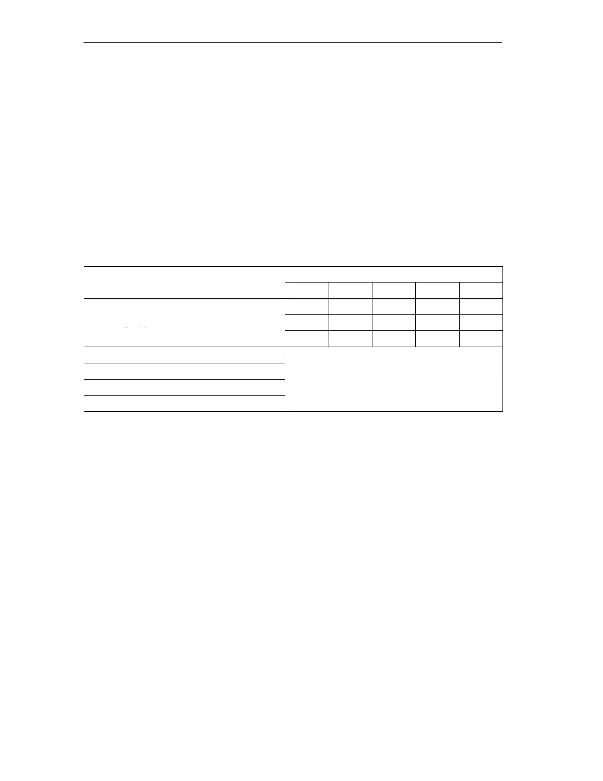
Table A-1 Structure of the Configuration Frame in the special identifier format (SKF)
Byte
Configured Address Area
n n + 1 n + 2 n + 3 n + 4
04 00 00 QD C4
Fixed range (byte 0 ... 14)
04 00 00 8B 41
04 00 00 8F C0
1st configured address area (byte 15 ... 19)
2nd configured address area (byte 20 ... 24)
See Table A-2
...
32nd configured address area (byte 170 ... 174)

 Loading...