*HWWLQJ6WDUWHG
Getting Started - ET 200S-IM 151/CPU Interface Module
A5E00058783-01
8-15
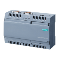
4 Add to the OB1 of the S7-300 CPU as shown below:
+RZLWZRUNVThe status of the switch connected to I1.1 of the S7-300 is queried
and temporarily stored in memory marker M13.0. The entire MB13 memory byte is
transferred to the PQB12 I/O output byte. You specified in the hardware
configuration in step 8 – Configuring the S7-300 (stage 9) – that the area from
PQW12 to PQW44 in the S7-300 CPU is to be assigned to the area from PIW128
to PIW160 in the IM 151/CPU.
In the IM program, PIB128 is transferred to the MB12 memory byte. The memory
marker M12.0 addresses output Q2.1.
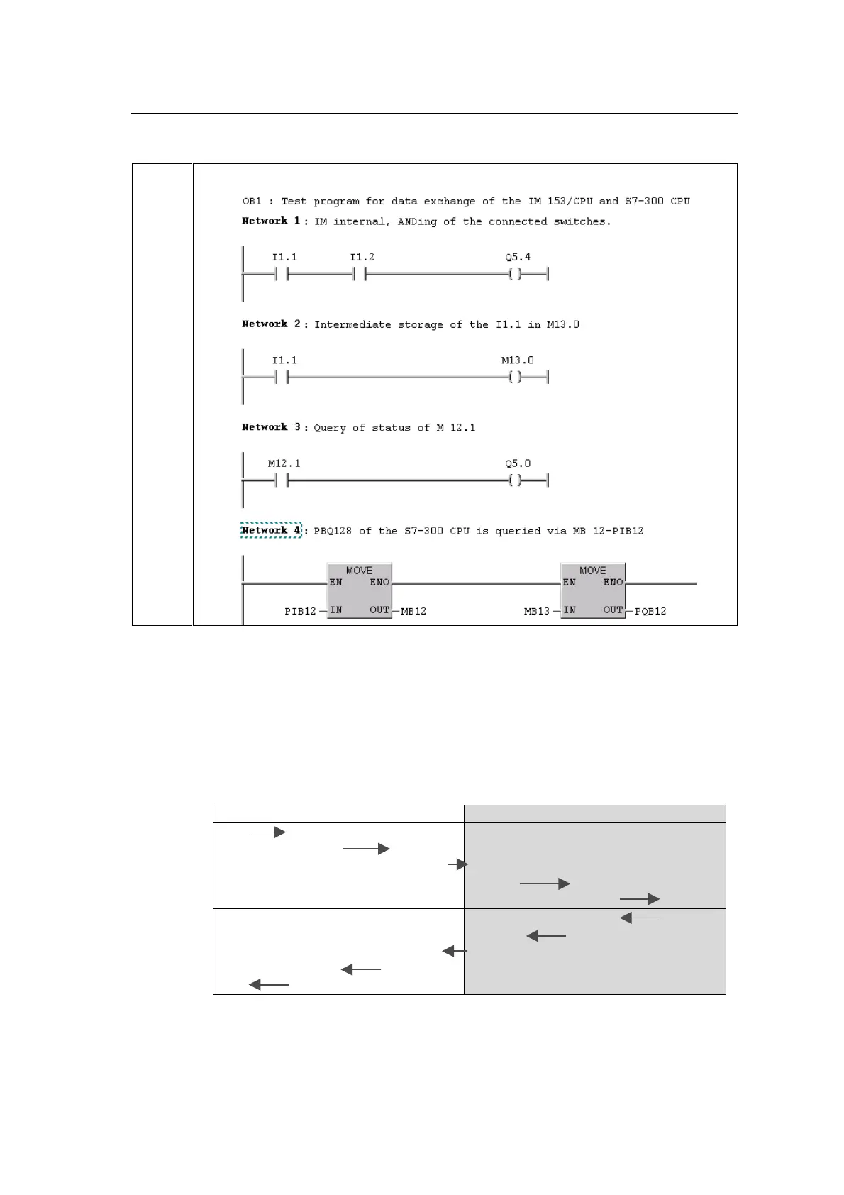
This results in the following communication paths:
6
,0&38
I1.1 M13.0
MB13 PQB12
PQW12
PIW128
PIB128 MB12
M12.0 Q2.1
PIW12
MB12 PIB12
Q5.0 M12.1
M13.1 I1.0
PQB128 MB13
PQW128

 Loading...