Structure of a CPU 41x
2.1 Control and display elements of the CPUs
S7-400 Automation System, CPU Specifications
2-2 Manual, 10/2006, 6ES7498-8AA04-8BA0
LEDs
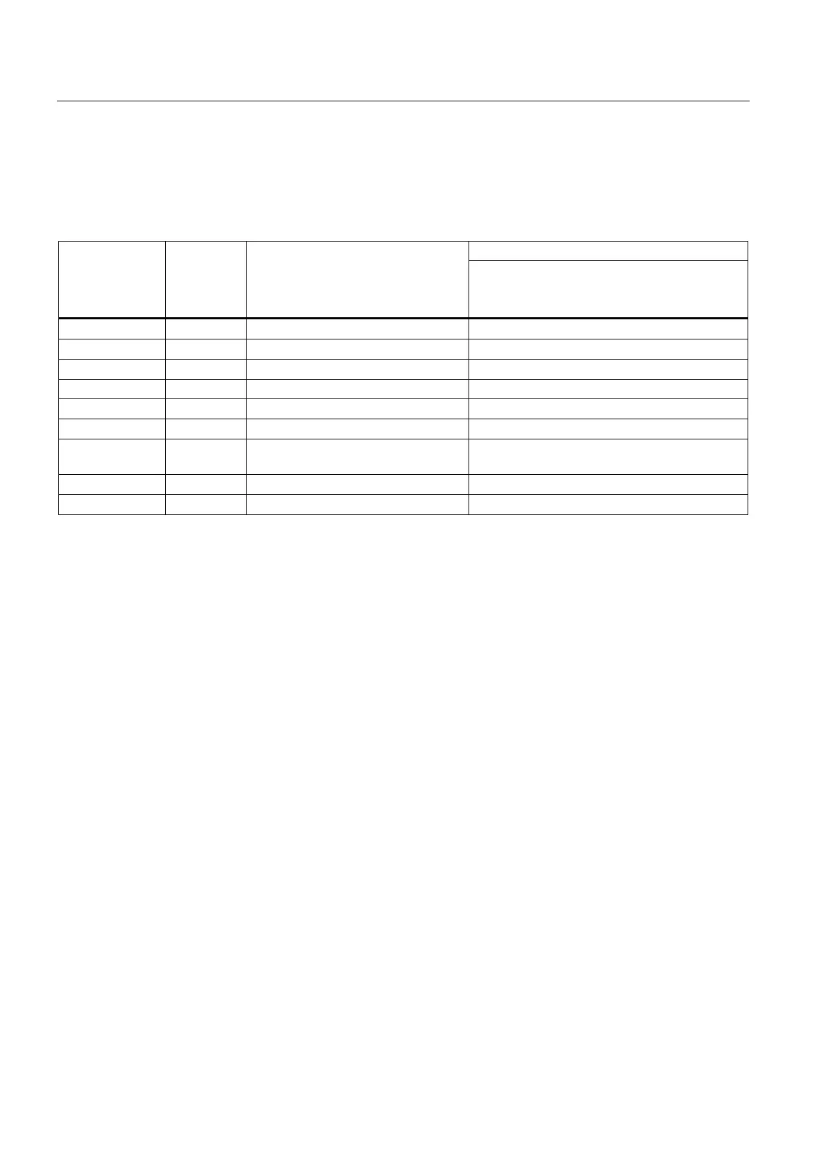
The table below gives you an overview of the LEDs on the individual CPUs.
Table 2-1 LEDs of the CPUs
Exists on CPU
LED Color Meaning
414-3 PN/DP
416-3 PN/DP
416F-3 PN/DP
INTF Red Internal fault x
EXTF Red External fault x
FRCE Yellow Force job active x
MAINT Not assigned x
RUN Green RUN mode x
STOP Yellow STOP mode x
BUS1F Red Bus fault on MPI/PROFIBUS DP
interface 1
x
BUS5F Red Features of the PROFINET interface x
IFM1F Red Fault on interface module 1 x
Mode Selector Switch
You can use the mode selector switch to set the current mode of the CPU. The mode
selector is a three-position toggle switch.
Memory Card Slot
You can insert a memory card into this slot.
There are two types of memory cards:
● RAM cards
You can expand CPU load memory with the RAM card.
● Flash cards
The flash card is non-volatile storage for storing your user program and data (no backup
battery necessary). You can program the flash card either on the programming device or
in the CPU. The flash card also expands the load memory of the CPU.
Slot for Interface Modules
You can insert one PROFIBUS DP module for the CPU 41x-3 and CPU 41x-4 in this slot.

 Loading...


