PROFIBUS DP
5.1 CPU 41x-3 PN/DP as DP master / DP slave
S7-400 Automation System, CPU Specifications
5-2 Manual, 10/2006, 6ES7498-8AA04-8BA0
5.1.2 DP address areas of 41x CPUs
Address Areas of 41x CPUs
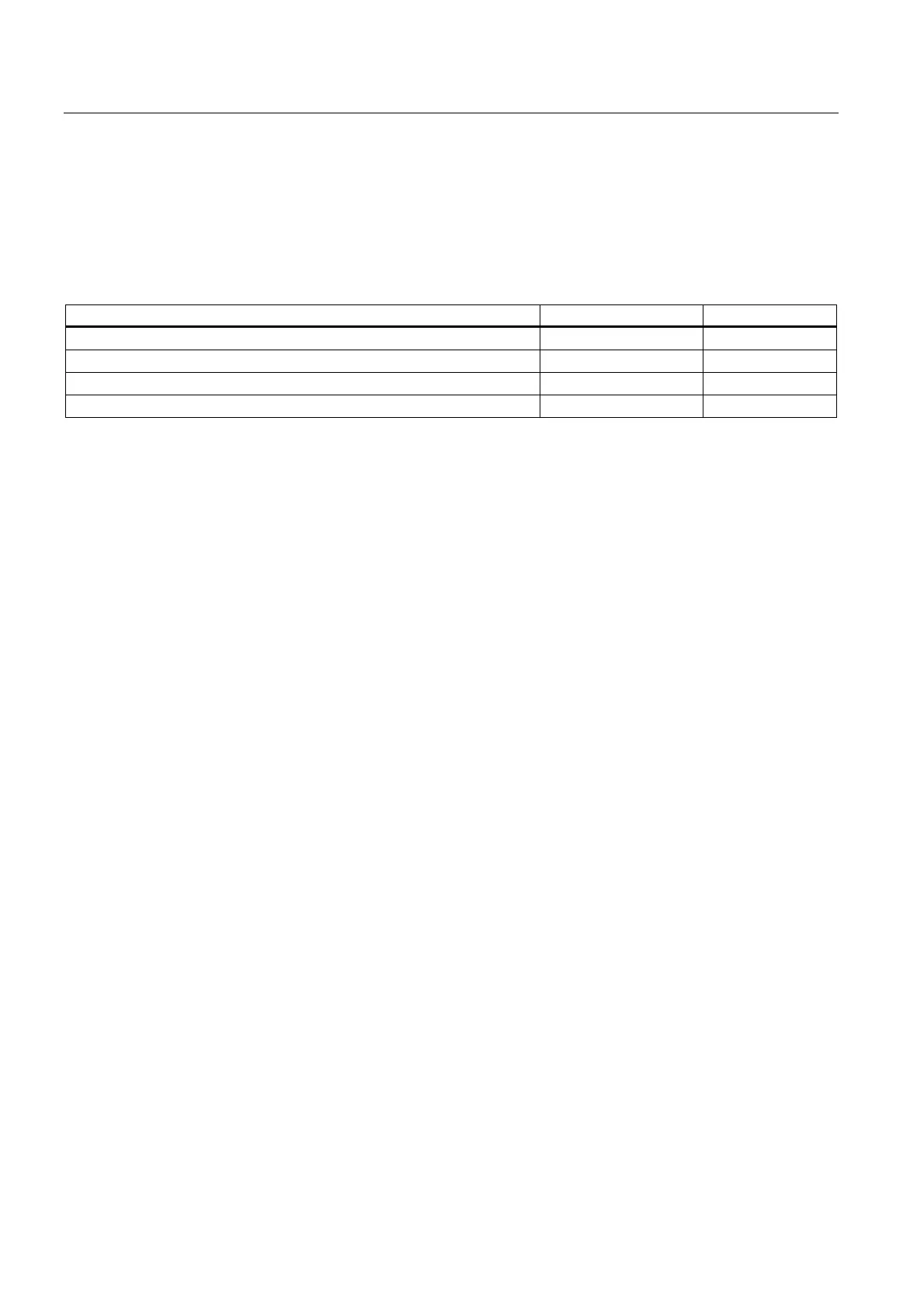
Table 5-1 41x CPUs (MPI/DP interface and DP module as PROFIBUS DP)
Address area 414-3 416-3
MPI interface as PROFIBUS DP, both inputs and outputs (bytes) 2048 2048
DP interface as PROFIBUS DP, both inputs and outputs (bytes) 6144 8192
DP module as PROFIBUS DP, both inputs and outputs (bytes) 6144 8192
In the process image, both inputs and outputs 8192 16384
In the input address area, the DP diagnostic addresses occupy at least 1 byte for the DP
master and each DP slave. The DP standard diagnostics for each node can be called at
these addresses, for example (LADDR parameter of SFC13). You specify the DP diagnostic
addresses during project engineering. If you do not specify DP diagnostic addresses,
STEP 7 assigns the addresses as DP diagnostic addresses in descending order starting at
the highest byte address.
In the DPV1 master mode, the slaves are usually assigned two diagnostic addresses.

 Loading...


