Installing and connecting the device
3.1 Preparing for installation
IFP V2, IFP V2 PRO, IFP V2 ETH
Operating Instructions, 03/2023, A5E46641410-AE
39
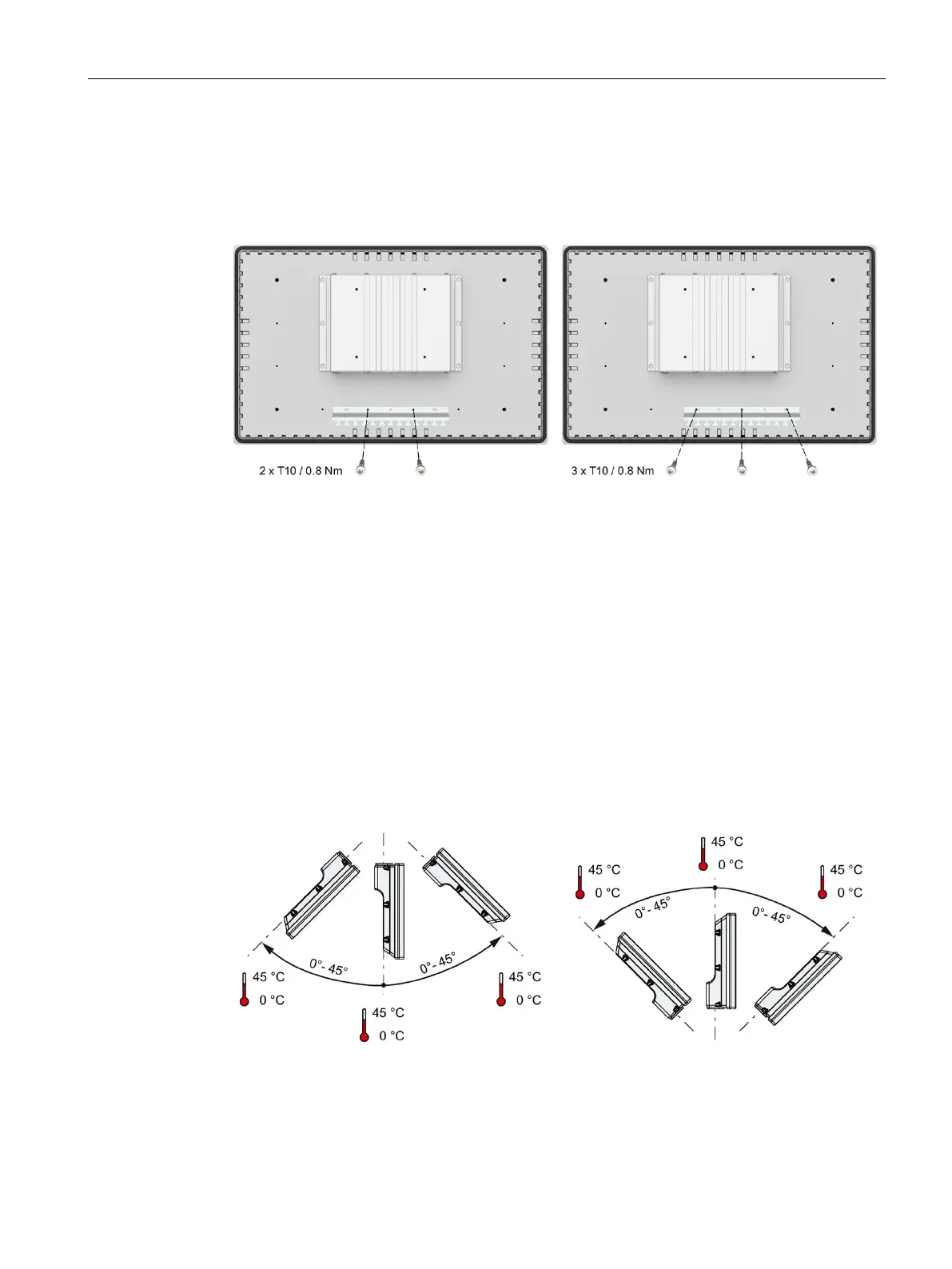
The following figures show central assembly and assembly to the right-hand side of the strain
relief plate as examples.
Strain relief plate, positioned in the center,
2 screws
Strain relief plate, positioned to the right,
3 screws
3.1.3 PRO devices
3.1.3.1 Permitted mounting positions
The device is intended for mounting on a support arm or stand.
Position the device in such a manner that safety-related devices such as a mains isolation
switch remain visible, accessible and operable.
The following figures show the permitted standard mounting positions of the different PRO
devices.
PRO devices for support arm (not extendable, flange top) and for pedestal (extendable,
flange bottom)
 Loading...