7
8
6
8-%-
7-
6-$-
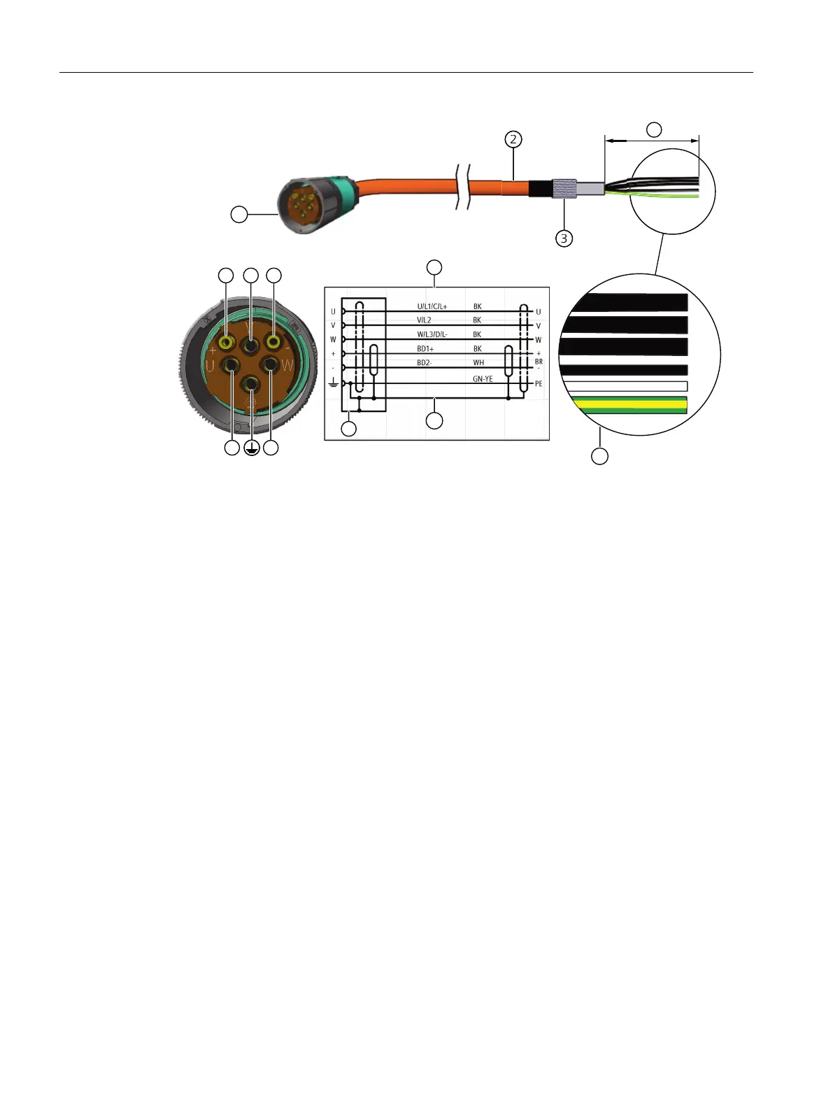
1 SPEED CONNECT connector, size M40
2 MOTION CONNECT cable
3 Cable shield
4 Connection diagram
U; V; W = power cables, 1.5mm
2
, 2.5mm
2
, 4mm
2
, 6mm
2
or 10mm
2
, each cable separately
shielded
BD1+ and BD2- = brake cable without lettering, 1.5mm
2
, shielded together
PE = protective conductor
5 Cable shield
6 Conductor designations
7 The length of the cable ends depends on the converter selected.
You can nd more information on connecting cables in chapter Connection notes (Page79).
Locking the round connectors
Properly lock the connected round connector at the motor.
Information on locking is provided in Chapter "Handling the quick-action locking (Page82)".
7.3.3 Signal connection
Signal connector design
The signal connection of the 1F☐2 is established using a round connector M17.
Connecting
7.3System integration
SIMOTICS S-1FT2 synchronous motors for SINAMICS S120
88 Operating Instructions, 12/2023, A5E50610821B AF
 Loading...