tA1.1
User
program
memory for:
onPA
AdAP e
oFPA
CLPA
hdEF
FdEF
FCon
FPoS
APSt
CAE4
CAE5
32 basic functions 109 arithmetic blocks
I,U,R
UNI,
P,
T,
V
+24V
+5V
U
REF
M
S3
L+
GND
GND
Options
1/22
1/21
Slot 3
Slot 2
Slot Te rmina l
RS 232/
RS 485
PROFIBUS
3AE
1AA y
hold
5BE
4BA24V
2BA R el.
3AA/3BE
4/2
4/7
4/8
4/3
–
AA1
AA2
AA3
BA1
2
3
4
5
6
7
BA8
1/12
1/13
1/14
1/4
1/5
1/6
1/7
1/8
1/9
1/10
1/11
6/6
6/5
6/4
6/3
6/2
6/1
5/6
5/5
5/4
5/3
5/2
5/1
1/20
1/19
1/24
1/23
2/4
2/3
2/2
2/1
3/4
3/3
3/2
3/1
1/15
1/16
1/17
1/18
1/3
1/2
1/1
L
N
PE
BE1
2
3
BE4
Front
module
0000
dA1.1...dA2.4
F
r
o
n
t
m
o
d
u
l
e
3AE
1AA y
hold
5BE
4BA 24V
+2BE
2BA R el.
3AA/3BE
AE1A
AE2A
AE3A
AE4A
AE5A
bE01
bE02
bE03
bE04
24 V
5V
dd1.1...dd3.4
L 1.1...L14.9
AA1.1...AA1.3
AA3.1...AA3.3
bA1.1...bA1.3
bA2.1...bA2.3
AA2.1...AA2.3
bA3.1...bA3.3
bA4.1...bA4.3
bA05
bA06
bA07
bA08
bE10...bE14
bA13...bA16
bE05...bE09
bA09...bA12
SA1.1...SA16.3
SAA1...SAA16
SbE1...SbE16
SbA1...SbA16
+
AE1
+
AE2
+
AE3
-
AE4
AE5
I,U
U
I,U
U
I,U
U
U
5V
24 V I
I
U
U
Slot 6
Slot 5
Slot 4
Options
Options
I
AFi1. AFi 2
Ain1...Ain4
bin1...bin6 c01.F...c33.F
CPt1, CPt2 with 4 inputs
dti1, dti2 1 output
FUL1, FUL2, FUL3
FUP1, FUP2
PUM1 - 4/SPR1 - SPR8
4 complex functions 4 arithmetic blocks
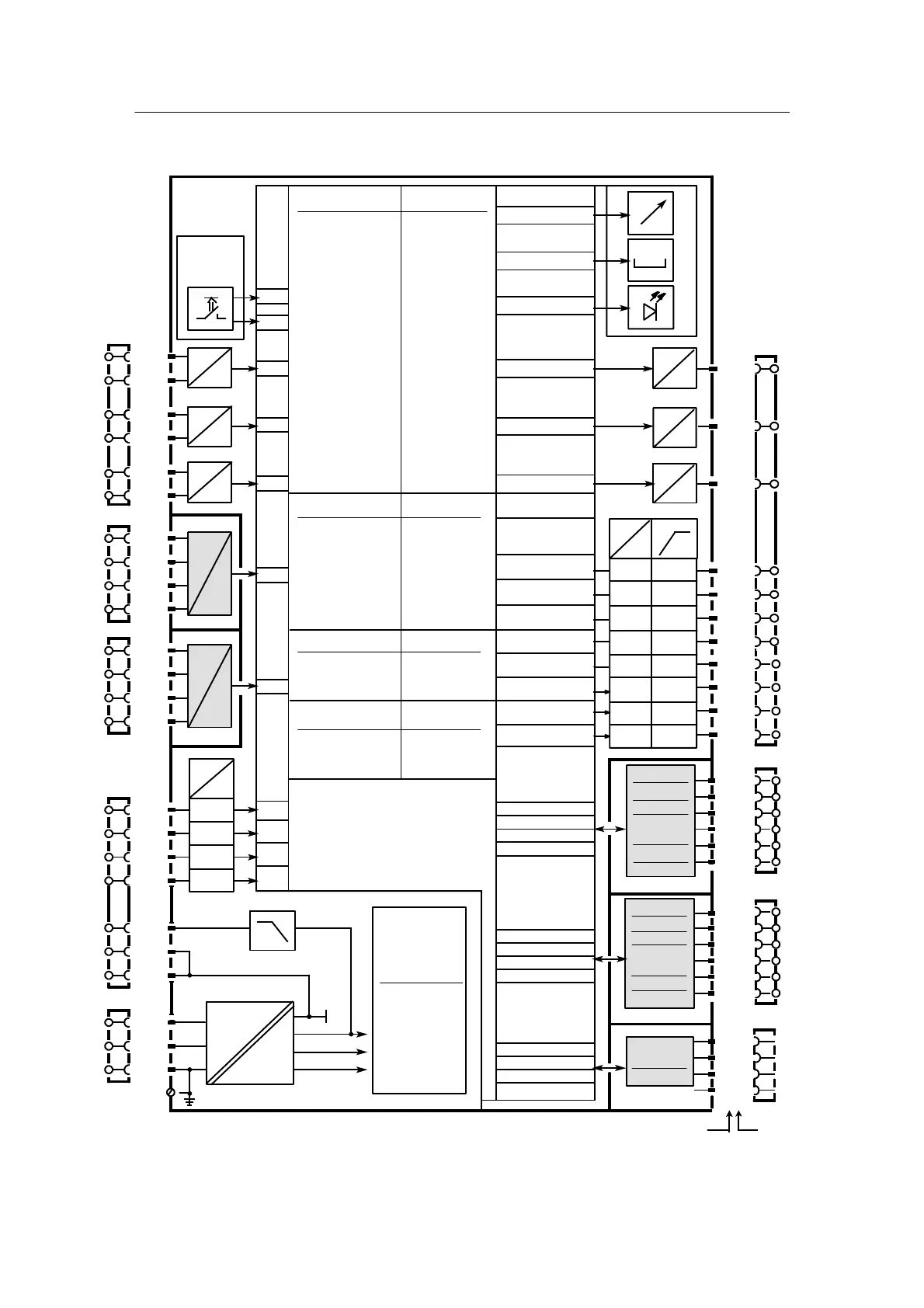
Figure 2-3 Block diagram SIPART DR24
6DR2410-4 24 V UC
6DR2410-5 115/230 V AC switchable
AE9A...AE11A
AA7...AA9
AE6A...AE8A
AA4...AA6
I
I
AbS, Add, AMEM,
AMPL, And,
ASo
bSo
CoMP, CoUn
dEbA, dEF, diF
div
Eor
FiLt b01 .F...bh9.F
LG, LiMi, LinE with 3 inputs
Ln 1 output
MAME, MASE
MiME, Mi SE
MULt
nAnd, nor
or
Pot
root
SUb
tFF, tiME
33 complex functions 33 arithmetic blocks
CLoc d01 .F...d04.F
MUP1, MUP2 with 12 inputs
Cnt1 14 outputs
12 complex functions 4 arithmetic blocks
Ccn1...Ccn4 h01. F...h04. F
CSE1...CSE4 with 18 i nputs
CSi1...CSi4 4 outputs
U
I,U,R
UNI,
P,
T,
V
U
tA7.F
#
online
offline
Manual
2 Installation
2.2 Electrical Connection
2.2.1 Block Diagram
SIP ART DR24 6DR2410
C79000-G7476-C153-03
111
2.2.1 Block Diagram

 Loading...


