2 Installation
2.2 Electrical Connection
2.2.2 Wiring of the standard Controller
Manual
112
SIP ART DR24 6DR2410
C79000-G7476-C153-03
2.2.2 Wiring of the standard Controller
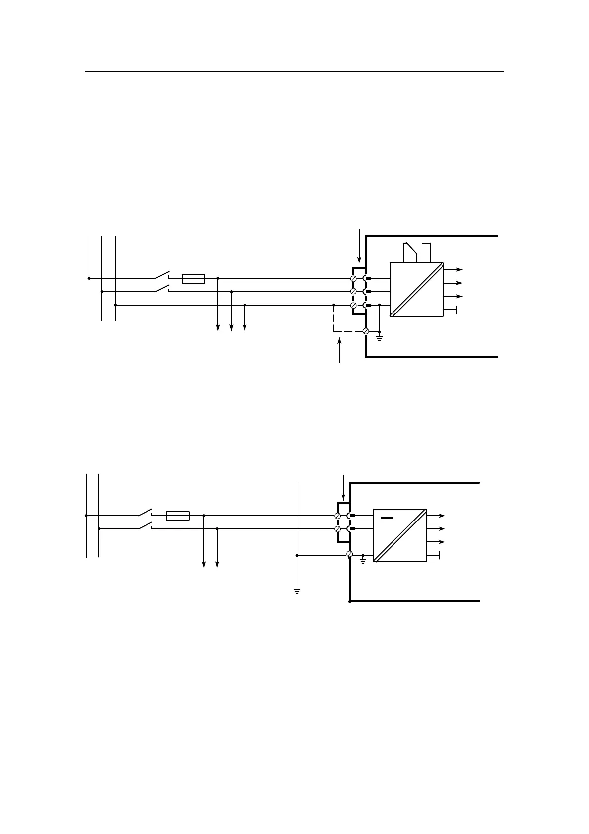
D Power supply connection
Attention:
Set mains voltage selection switch (see fig. 2-1, page 109) in no--voltage state according to
the available mains voltage!
- 6DR2410-5 115/230 V AC, switchable
Three-pin plug IEC 320 IV
DIN 49457A
1A slow blow per controller
L
NPE
230 115
~
=
+24V
+5V
U
REF
other loads in the same si-
gnal loop; use larger fuse
if necessary
Alternative
DR24
6DR2410-5
115 or 230 V AC
L
N
PE
Figure 2-4 Wiring diagram of power supply 115/230 V AC
- 6DR2410-4 24V UC
Special 2--pin plug
any polarity
=
other loads in the same
signal loop; use larger-
fuse if necessary
DR24
6DR2410--4
3.15A slow blow per controller
µ
24 V UC
+24V
+5V
U
REF
Figure 2-5 Wiring diagram of power supply 24 V DC

 Loading...


