Manual
2 Installation
2.2 Electrical Connection
2.2.4 Alternative Wiring for I- and U Input
SIP ART DR24 6DR2410
C79000-G7476-C153-03
123
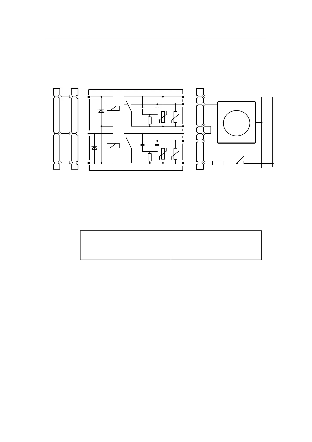
D 6DR2804-8A (interface relay 230 V, 4 relays)
6DR2804-8B (interface relay 230 V, 2 relays)
E.g. wiring for
Δy outputs in the S-controller with interface relay 230 V, 2 relays
(6DR2804-8B)
1/10
420 V
420 V
GND
BA7
+Δy
BA8
--Δy
220 Ω
33n
1/1
1/11
220 Ω
33n
N
L
7/1
7/2
7/3
7/6
7/4
7/5
7/9
7/7
7/8
GND
Figure 2-26 Wiring of interface relay 230 V 6DR2804-8B
The interface relay 230 V, 4 relays (6DR2804-8A) contains 4 relays. Terminals 8/1 to 8/9 must
then be connected accordingly in addition to the terminals 7/1 to 7/8.
Attention: Observe the max. switching voltage! (resonance sharpness in phase shift motors,
see chapter 1.4.2, page 12)
AC
250
8
1250
V
A
VA
DC 250
8
30
100
V
A
W at 250 V
Wat24V
2.2.4 Alterna tive Wiring for I- and U Input
D 0/4to20mAsignals
The 49.9 Ω input impedance is connected across the input signals AE+ and AE-- (AE1 to
AE3 in the standard controller and in module 6DR2800-8A by means of jumper settings and
by external wiring on the option module for AE4 and AE5).
If the signal is still required during service work in which the terminal is disconnected, the
49.9 Ω 0.1 % input impedance must be connected to the terminal between AE+ and AE--.
The internal 49.9 Ω resistance must then be disconnected by appropriate jumper settings or
by rewiring.

 Loading...


