2 Installation
2.2 Electrical Connection
2.2.5 Wiring of the Interface
Manual
128
SIP ART DR24 6DR2410
C79000-G7476-C153-03
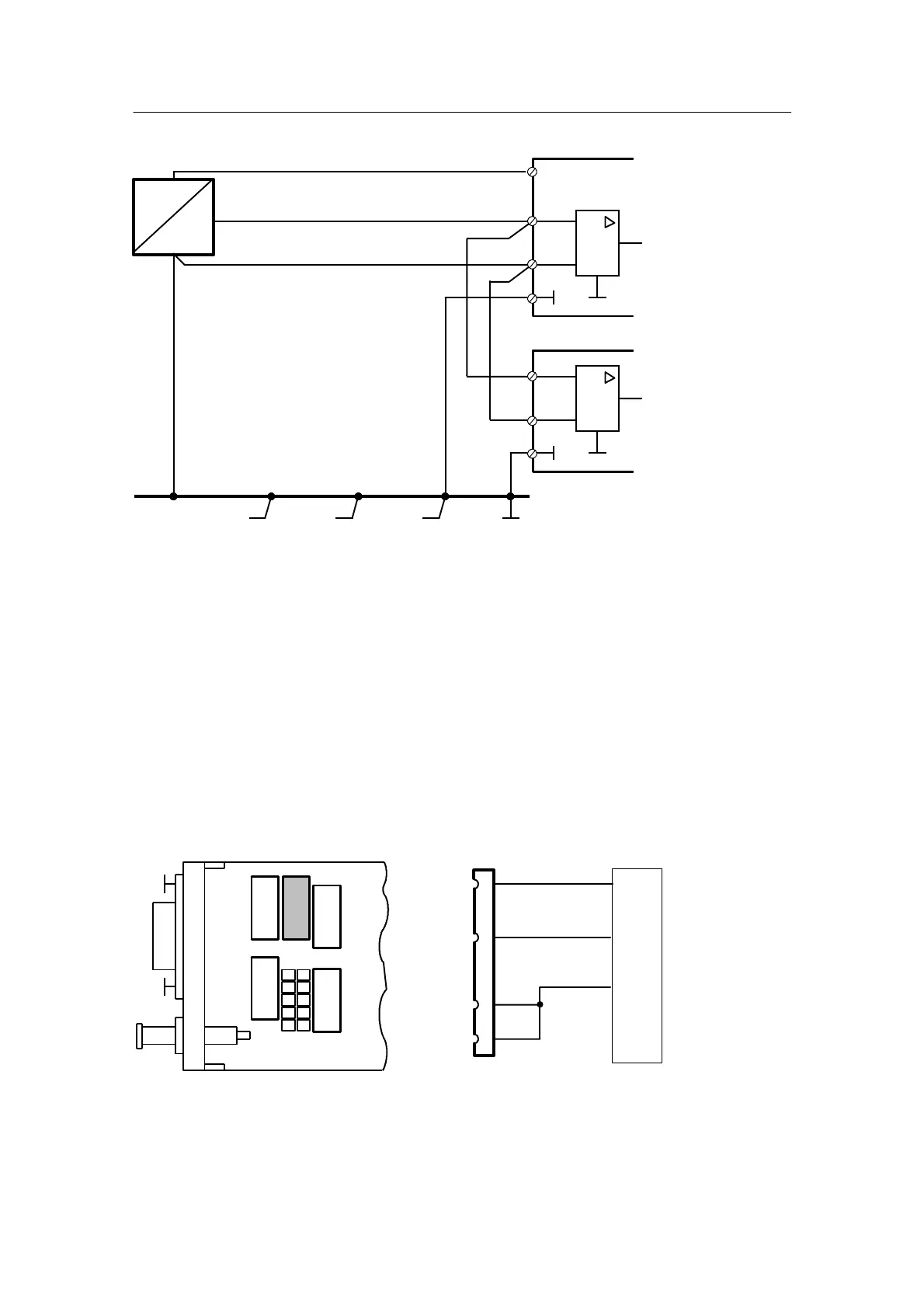
U
+
+
--
Instrument 1
Instrument 2
AE+
AE--
M
+
AE+
AE--
GND
L+
--
--
Figure 2-38 Parallel wiring of a non--floating voltage supply to two instruments. The voltage source is
supplied by L+ of one of the instruments and negative polarity is referred to ground.
Figure 2-37 and Figure 2-38:
The voltage dip on the ground rail between the voltage source and the input amplifier appears
as a common mode voltage and is suppressed.
2.2.5 Wiring of the Interface
D Wiring of the interface module 6DR2803-8C
- RS 232 point--to--point (END/END)
Canbeinsertedinslot4
RS 485
Rxd
Controller
Remote
system
4/2
4/3
4/7
4/8
Txd
Reference
2
3
5
RS 232
END/END
SIPART
BUS
RS 485
+150 R
Figure 2-39 Setting on the SES module 6DR2803-8C with RS 232 point--to--point and wiring

 Loading...


