3 Operation
3.3 Configuring Mode (Parameterization and Configuring Mode)
3.3.2 Parameterization Mode AdAP (Adaptation)
Manual
138
SIP ART DR24 6DR2410
C79000-G7476-C153-03
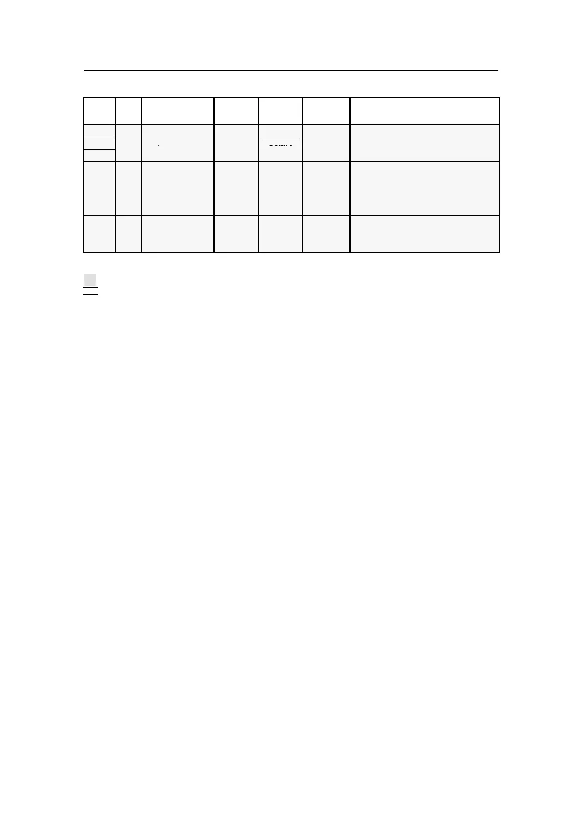
dd2 Parameter meaning
Dimen-
sion
Resolu-
tion
Factory
settin g
dd1
Setting range
dd3
dti1
Dead time element 1
↓
td oFF, 1.000 to 9984 1
va
ues
Octave
s
dead time
dt12
Dead time element 2
PUM1
↓
PUM4
tAE
tM
20 to 9980
0.100 to 1000
20
0.100
20
128 va-
lues/oc-
tave
ms
s
Pulse width modulator 1 reduces turn--on time
4 period duration
Spr1
↓
Spr8
SPA
SPE
0.0 to 100.0
0.0 to 100.0
0.0
100.0
0.1
0.1
%
%
Split range 1 foot point
8 corner point
1)
YE > YA, LiE > LiA
omitted if not defined in FdEF
Fast action jumps
Table 3-1 Online parameters in parameterization mode onPA
3.3.2 Parameterization Mode AdAP (Adaptation)
This mode appears in the parameter preselection mode only when the control input AV is High
and the block is positioned in FPoS in one of the defined controllers (blocks h*.F). The Enter
function into the parameterization mode AdAP can only be used if the controller selected for
adaptation is in manual mode.
In the parameterization mode AdAP, the SIPART DR24 acts online on the process (but the cor-
responding controller is in manual mode).
The necessary process displays can be provided during adaptation by appropriate connection
with the controller output AL (adaptation in progress) in connection with the indicators and
switching functions.
The parameterization mode AdAP has 4 different statuses (described in detail below):
D pre adaptation
D during adaptation
D aborted adaptation
D post adaptation
The digital displays dd1 to dd3 and the keys get different functions in the individual statuses
which can be included in the controller operating concept without any hitches.
The digital displays and the keys are used before and after adaptation for the parameter display
and - setting as is the case in the parameterization and configuring modes onPA or oFPA (see
figure 3-6, page 142).
The complete connected process image as described in chapter 3.1 is displayed during adapta-
tion (see figure 3-7, page 142).

 Loading...


