2 Functions
154
7UT613/63x Manual
C53000-G1176-C160-2
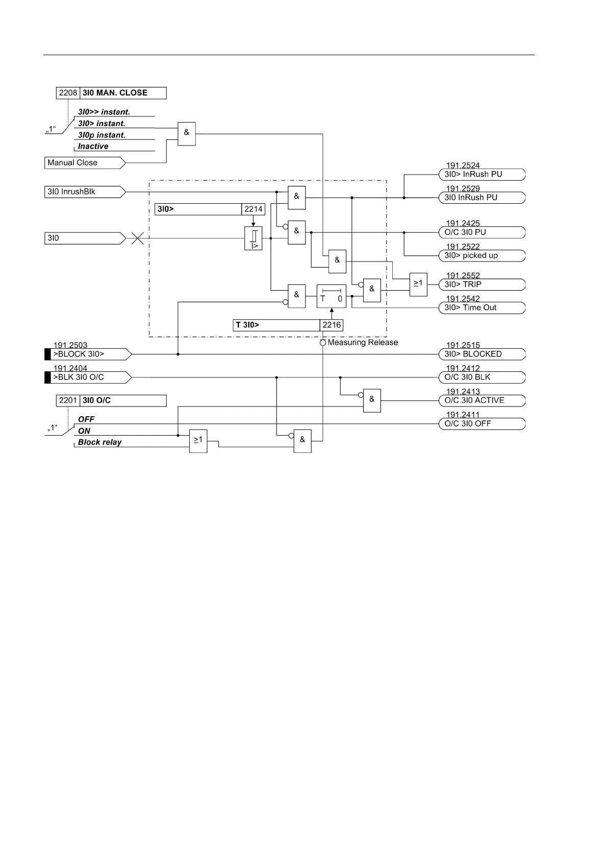
Figure 2-68 Logic diagram for the overcurrent stage 3I0> for residual current (simplified)
The pickup values of all stages I> (phases), 3I0> (zero sequence current), I>>
(phases), 3I0>> (zero sequence current) and the time delays associated for each
stage can be set individually.
2.4.1.2 Inverse Time Overcurrent Protection
The inverse-time overcurrent protection stages always operate with a characteristic
either according to the IEC or the ANSI standards or according to a user-defined char-
acteristic. The characteristics and their equations are displayed in the Technical Data.
When configuring one of the inverse time characteristics, definite time stages I>> and
I> are also enabled.
Pickup, Tripping Each phase current and the zero sequence current (sum of phase currents) are com-
pared individually to a common setting value Ip or 3I0p. If a current exceeds the
setting value by 1.1 times, the corresponding stage picks up and is signalled selective-
ly. If inrush restraint is used, a frequency analysis is performed first. Depending on the
detection of inrush currents, either normal pickup annunciations or relevant inrush
messages are issued. For pickup, the RMS values of the fundamental harmonics are
used. During the pickup of an I
p
stage, the tripping time is calculated from the flowing
fault current by means of an integrating measuring procedure, depending on the se-
 Loading...


