4.22 Additional Functions
487
7UT613/63x Manual
C53000-G1176-C160-2
4.22 Additional Functions
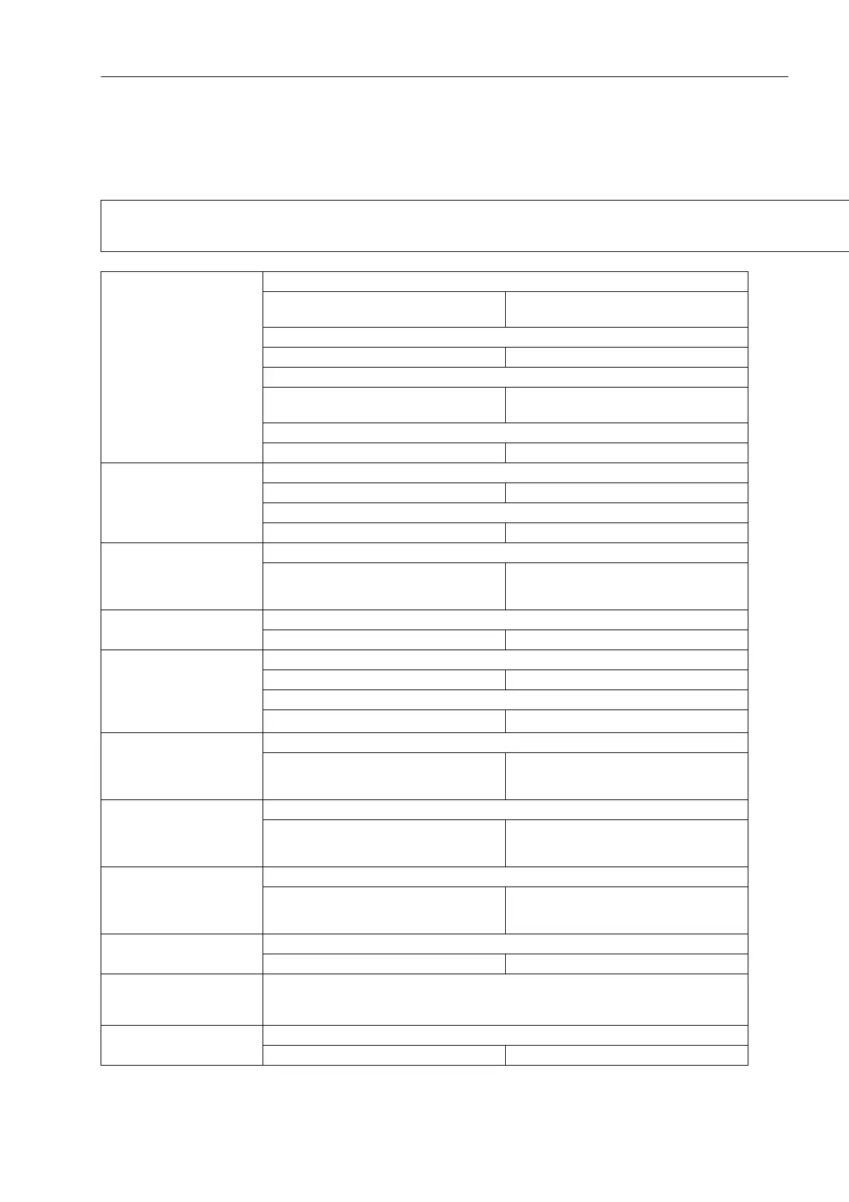
Operational Measured Values
Note:
The tolerances stated in the data below refer to one measuring location or one side with
2 measuring locations. All values are ± digit.
Operational measured
values for currents
3-phase
(for each measuring loca-
tion)
I
L1
; I
L2
; I
L3
in A primary and secondary
– Tolerance with I
N
=1A or 5A
– Tolerance with I
N
=0.1A
1 % of the measured value or 1 % of I
N
2 % of the measured value or 2 % of I
N
3I
0
; I
1
; I
2
in A primary and secondary
– Tolerance 2 % of measured value, or 2 % of I
N
I
L1
; I
L2
; I
L3
in A primary and in % I
N Side
– Tolerance with I
N
=1A or 5A
– Tolerance with I
N
=0.1A
1 % of the measured value or 1 % of I
N
2 % of the measured value or 2 % of I
N
3I
0
; I
1
; I
2
in A primary and in % I
N Side
– Tolerance 2 % of measured value, or 2 % of I
N
Operational measured
values for currents
1-phase
I
1
to I
12
or I
Z1
to I
Z4
in A primary and secondary and in % I
N
– Tolerance 2 % of measured value, or 2 % of I
N
for sensitive current inputs in A primary and mA secondary
– Tolerance 1 % of measured value or 2 mA
Phase angle currents
3-phase
(for each measuring loca-
tion)
ϕ(I
L1
); ϕ(I
L2
); ϕ(I
L3
) in ° referred to ϕ(I
L1
)
– Tolerance 1° at rated current
Phase angle currents
1-phase
ϕ(I
1
) to ϕ(I
12
) or ϕ(I
Z1
) to ϕ(I
Z4
) in ° referred to ϕ(I
1
)
– Tolerance 1° at rated current
Operational values for volt-
ages
(3-phase, if voltage
connected)
U
L1-E
; U
L2-E
; U
L3-E
; U
L1-L2
; U
L2-L3
; U
L3-L1
in kV primary and V secondary and % U
Nop
– Tolerance 0.2 % of setting value or 0.2 V
U
1
; U
2
; U
0
in kV primary and V secondary and % U
NOp
– Tolerance 0.4 % of setting value or 0.4 V
Operational values for volt-
ages
(1-phase, if voltage
connected)
U
EN
or U
4
in kV primary and V secondary and % U
Nop
– Tolerance 0.2 % of setting value or 0.2 V
Phase angle of
voltages
(3-phase, if voltage
connected)
ϕ(U
L1-E
); ϕ(U
L2-E
); ϕ(U
L3-E
) in ° referred to ϕ(I
1
)
– Tolerance 1 ° at rated voltage
Phase angle of
voltages
(1-phase, if voltage
connected)
ϕ(U
EN
) or ϕ(U
4
) in ° referred to ϕ(I
1
)
– Tolerance 1 ° at rated voltage
Overexcitation Factor (U/f) / (U
N
/f
N
)
– Tolerance 2 % of measured value
Operational measured
values of frequency
Frequency
f in Hz and % f
N
Range 10 Hz to 75 Hz
– Tolerance 1 % in range f
N
± 10 % at I = I
N
 Loading...


