3.1 Mounting and Connections
373
7UT613/63x Manual
C53000-G1176-C160-2
• Alternatively, there is the possibility to connect the aforementioned earthing to the
lateral grounding surface with at least one M4 screw.
• Connections according to the circuit diagram via screw terminals, connections for
optical fibres and electrical communication modules via the console housing. The
SIPROTEC 4 System Description /1/ has pertinent information regarding wire size,
lugs, bending radii, etc. Installation notes are also given in the brief reference
booklet attached to the device.
3.1.3.4 Removing the Transport Protection
Devices in housings size
1
/
1
(7UT633 and 7UT635) for surface mounting are delivered
with a transport protection (Figure 3-20). This protection must not be removed until the
device has arrived at its final place of use.
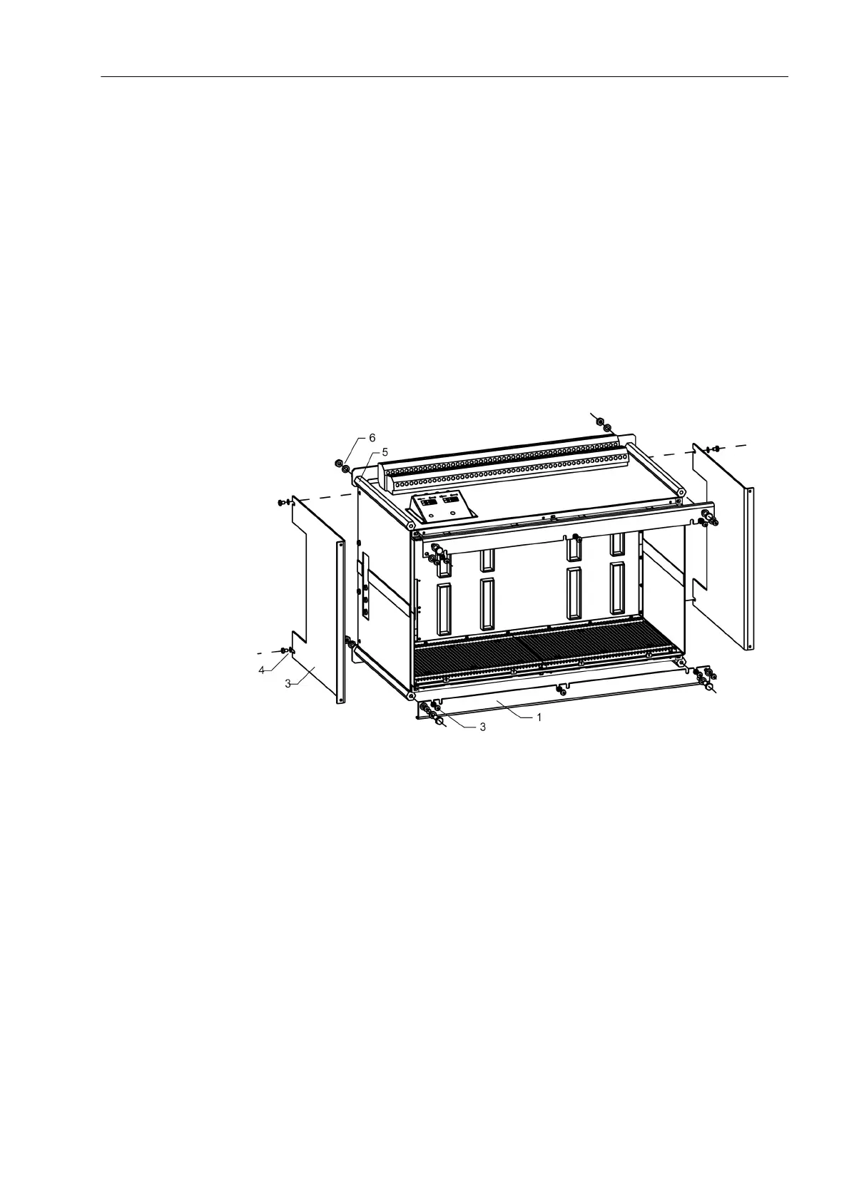
Figure 3-20 View of a housing with transport protection (without front cover nor boards)
• Remove the 4 covers at the corners and the 2 covers in the centre above and below
on the front cover to reveal 6 elongated holes.
• Loosen the 6 screws (2) in the elongated holes.
• Remove all other screws on the rails (1) and remove the top and bottom rails.
• Loosen the 2 screws each (4) in the elongated holes on the right and left side walls
(3), and remove the side walls.
• Firmly tighten again all 10 screws that you loosened.
• Attention! If the device is pre-mounted, e.g. on a mounting panel, and secured with
a transport protection, do not remove all bolts at once. In such a case, remove only
one bolt at a time and immediately re-screw the device to the mounting panel at the
place where you removed the bolt.
• Remove the nuts and washers (6) from the 4 bolts (5), and remove the bolts.
• The device can now be secured to the panel with four screws.
 Loading...


