3 Mounting and Commissioning
410
7UT613/63x Manual
C53000-G1176-C160-2
• The checks must be performed on one device per phase for each phase. In the fol-
lowing you can find some more information on summation transformers.
• However, each check is restricted on one current pair, i.e. on the one traversing
testing current. Information on vector group matching and vectors (except the
phase angle comparison of the traversing current = 180° at the sides tested) or
similar is not relevant.
Summation Trans-
former Connection
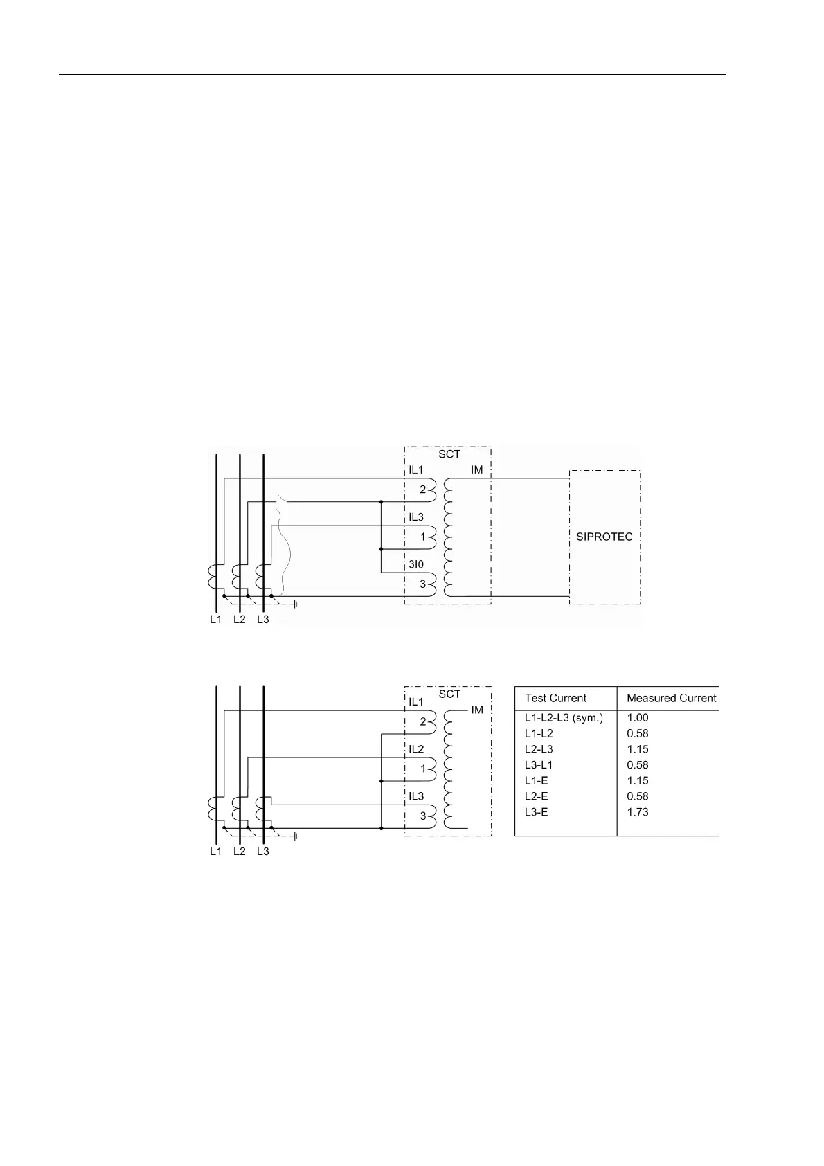
If summation transformers are used, different connection possibilities exist. The fol-
lowing clarifications are based on the normal connection mode L1-L3-E. This connec-
tion variant and the connection mode L1-L2-L3 are shown in the following figures.
Single-phase primary tests are to be preferred, since they evoke clearer differences in
the measured currents. They also detect connecting errors in the earth current path.
The measured current to be read out in the operational measured values only corre-
sponds to the testing current if three-phase symmetrical check is performed. In other
cases there are deviations which are listed in the figures as factor of the testing cur-
rent.
Figure 3-37 Summation Transformer Connection L1-L3-E
Figure 3-38 Summation transformer connection L1-L2-L3
Deviations which cannot be explained by measuring tolerances may be caused by
connection errors or matching errors of the summation transformers:
• Switch off the test source and the protected object and earth it,
• Check the plant connections to the device and the test arrangement and correct
them.
• Repeat test and re-check the current magnitudes.
 Loading...


