 Loading...
Do you have a question about the Siemens sitrans PROBE LU and is the answer not in the manual?
| Measuring Principle | Ultrasonic |
|---|---|
| Communication | HART |
| Output | 4 to 20 mA |
| Power Supply | 12 to 30 V DC |
| Process Temperature | -40 to 80 °C |
| Enclosure Rating | IP68 |
| Material | PVDF |
| Ambient Temperature | -40 to 70 °C |
| Measurement Range | 0.25 to 12 m (0.8 to 39 ft) |
Symbols used for warnings and instructions.
Information regarding the manual's content and purpose.
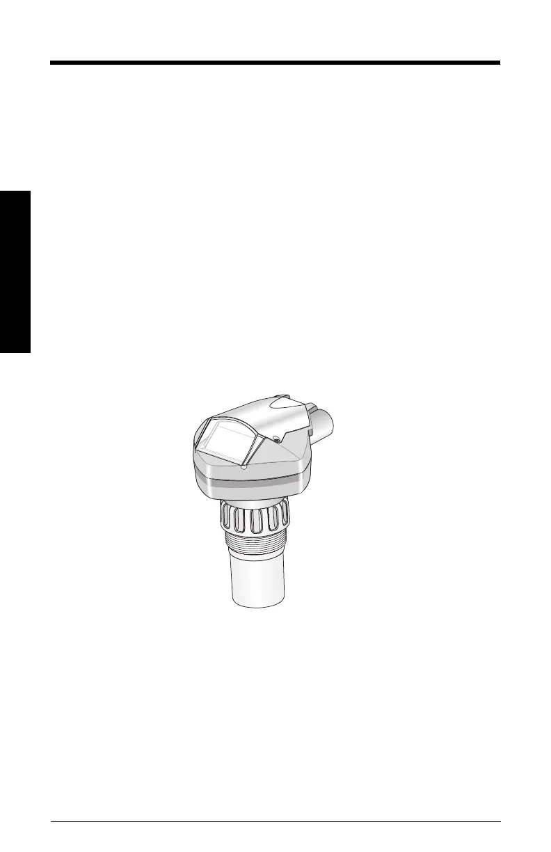
Illustrative examples of typical SITRANS Probe LU installations.
List of common abbreviations and their meanings.
Describes the device's capabilities in measuring levels, volumes, or flow rates.
Details on integrating the SITRANS Probe LU into system configurations.
Information on how to program the device parameters.
Listings of device certifications and approvals.
Technical details on power consumption and performance metrics.
Physical dimensions, connections, and interface details.
Operating conditions and safety/regulatory approvals.
Description of the device's startup sequence and RUN mode display.
Steps to enter the device's program mode.
Explanation of the programmer's navigation and editing functionalities.
How parameters are displayed in program mode.
Configuration options for device security and access control.
Instructions for performing a master reset on the device.
Initial steps to power up and activate the device.
Procedure for configuring the device's PROFIBUS network address.
Guide to calibrating the device using PROFIBUS PA.
Methods for modifying device parameters.
Detailed steps for device calibration.
Technique for managing false echoes affecting measurements.
An example demonstrating a level measurement application.
Information on using SIMATIC PDM for device configuration and management.
Details on obtaining and using the device description file.
Steps for configuring the device using GSD files.
Network addressing and bus termination requirements.
Calculating power requirements for the PROFIBUS network.
Response format for cyclic diagnostic requests.
Diagnostic information obtained via acyclic communication.
Explanation of the ultrasonic measurement technology.
Configuration of device reaction speed to level changes.
How the device verifies echo signals.
Handling of echo loss conditions and associated timers.
Device behavior during failsafe conditions.
Setting failsafe output values and near range blanking.
Techniques for mitigating false echo readings.
Feature for converting level to flow rates in open channels.
Information on material resistance to chemicals.
Common fault codes and recommended troubleshooting actions.
Guidelines for device repair and warranty information.
Overview of the device's parameter menu hierarchy.
Explanation of information shown on the device's LCD screen.
Detailed instructions for operating the handheld programmer.
Key functions available when the programmer is in RUN mode.
How to navigate and edit parameters using the programmer.
Configuration of local operation, remote lockout, and write locking.
Procedure for resetting the device to factory defaults.
How to reset specific parameters to their default values.
Steps to reset fault messages after correction.
Comprehensive guide to calibrating the device's sensors.
Visual map of the device's menu system and parameters.
Overview of the device's adherence to PROFIBUS PA profiles.
Description of the device's functional block structure.
Details on the LTB's role in measurement processing.
Explanation of AIFBs for data output and scaling.
Functional explanation of the Level Transducer Block.
How AIFBs process data and handle simulation.
In-depth explanation of AIFB functions, including output conversion and failsafe.
Organization of device data and physical block information.
Mapping of parameter indices to their names and types.
Parameters related to device and sensor lifespan tracking.
Data structure for Analog Input Function Blocks.
Detailed breakdown of the LTB's structure and parameters.
Specific definitions for LTB parameters like SV1, SV2, and offsets.
Guide to navigating and accessing device parameters.
Parameters for device identification and basic configuration.
Parameters for device management, resets, and lockout.
Parameters related to device identification, serial numbers, and firmware revisions.
Parameters for user interface control and access protection.
Parameters for tracking device usage statistics and temperatures.
Parameters related to transducer temperature and input settings.
Configuration of the device's reaction speed to measurement changes.
Settings for echo verification and measurement reliability.
Parameters for calculating sound velocity using temperature data.
Setting the device's current consumption for the PROFIBUS network.
Defining sensor units and selecting calibration methods.
Setting calibration points and engineering units for level measurement.
Configuring sensor offsets and defining measurement range limits.
Setting minimum/maximum sensor values and process temperature limits.
Configuring linearization for volume or level conversion based on tank shape.
Defining volume calculation parameters based on tank geometry.
Parameters for tank dimensions and failsafe response configuration.
Configuring volume breakpoints for complex tank shapes.
Step-by-step guide for entering breakpoints using PDM.
Using breakpoints for calculating flow rates in open channels.
Configuring breakpoints for head level and flow measurements.
Selecting algorithms for echo profile analysis.
Configuring sound velocity compensation and calibration.
Settings for acquiring echo samples for measurement.
Configuring echo sampling direction and measurement window.
Defining the minimum and maximum measurement distances.
Metrics for evaluating echo signal reliability.
Displaying the amplitude of the selected echo signal.
Configuring the Time Varying Threshold curve.
Enabling automatic filtering of false echo signals.
Setting the distance for the auto false echo suppression feature.
Enabling or disabling the TVT shaper function.
Adjusting the TVT curve shape for signal processing.
Configuring the maximum rates for level increase and decrease.
Diagnostic values from the transducer block.
Settings for the first Analog Input Function Block.
Configuring output units, filter time, and function type.
Parameters for batch processing applications.
Scaling input and output values for measurement display.
Setting alarm and warning thresholds for output values.
Configuring hysteresis for alarms and defining min/max output values.
Defining device reaction to failsafe conditions and setting failsafe values.
Configuring decimal points and output unit text.
Information on device certifications and compliance.
Monitoring the remaining operational lifetime of the device.
Monitoring the remaining operational lifetime of the sensor.
Configuring maintenance and calibration schedules.
Configuring how status information is reported.
Wiring requirements for intrinsically safe installations.
General safety and installation guidelines for hazardous locations.
Explanation of the FISCO concept for safe interconnection.
Specific requirements for FM and CSA certifications.
Equivalency of safety barriers for EU hazardous area classifications.