Page 58 SITRANS Probe LU (PROFIBUS PA) – INSTRUCTION MANUAL 7ML19985JB02
mmmmm
F: Profile structure
3. Then linearization can be carried out to accommodate complex tank shapes, or to
provide level to volume conversion.
4. The LTB provides four possible outputs
• Primary Value (PV) / Level or Volume
• Secondary Value 1 (SV1) / Level
• Secondary Value 2 (SV2) / Distance 1 (sensor units)
• Secondary Value 3 (SV3) / Distance 2 (any level units, except %)
Electronics temperature
The transducer block also monitors the internal temperature of the device electronics. If
the temperature exceeds permitted limits, it does not change the sensor value, but it does
change the status.The permitted limits correspond to the permitted ambient temperature
limits.
If a temperature limit is exceeded, the status changes. Peak indicators
1
allow you to
check the maximum and minimum temperatures that have occurred.
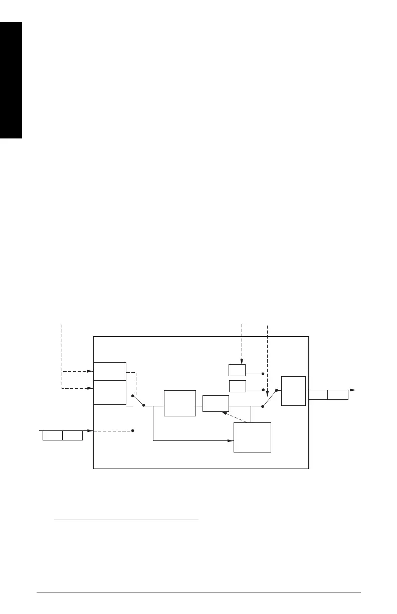
Analog Input Function Blocks 1 and 2
The figure below shows how measured values are processed within the two Analog
Input Function Blocks to produce the device outputs, which are communicated via cyclic
transfer to PROFIBUS PA, and displayed on the LCD.
Analog Input Function Block function groups (simulation, mode, and status)
2
1.
Open View menu, scroll down to Peak Values, and click on Temperature tab in the
Peak Values window.
2.
The output from the Level Transducer Block can be called the Primary Value (PV) or
Secondary Value (SV1, SV2, or SV3). When it becomes the input to the AIFB, it is called
the Process Variable.
enable
on
FB
algorithm
Status
OUT
AUTO
MODE and
STATUS
handling
Process Variable
2
from LTB
(Function Block
input)
Value
Status
Alarm
Limit
Check
Out of
Service
OUT
OUT
MAN
Value
simulate
value and
status
Value Status
Operator
Operator
off
Simulate
Parameter
Failsafe
 Loading...