7ML19985JB02 SITRANS Probe LU (PROFIBUS PA) – INSTRUCTION MANUAL Page 107
mmmmm
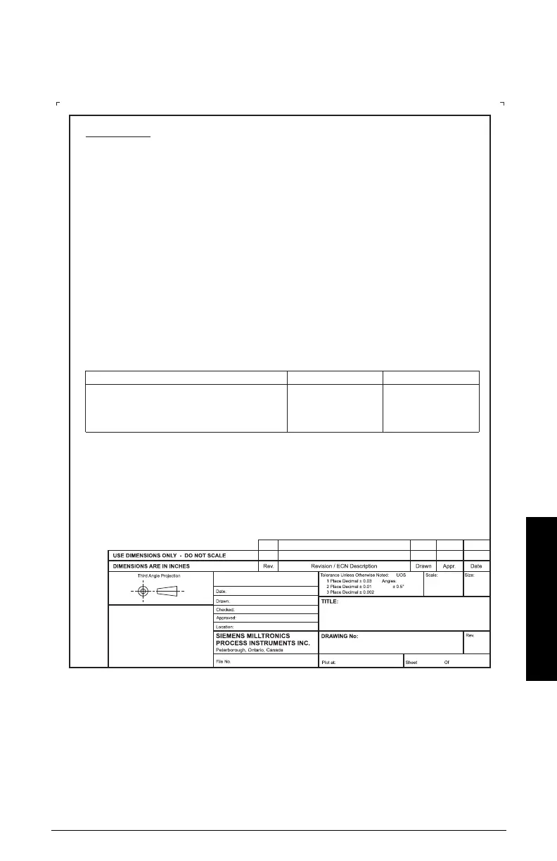
J: Hazardous installation
Intrinsically Safe wiring drawing (FM/CSA)
Product Group
FOR INTERNAL
USE ONLY
S. NGUYEN
PETERBOROUGH
FOR CONSTRUCTION0
E. DeSIMONE
R. CLYSDALE
1:1
14
NTS
A
0
RPC
SN
FISCO-Concept
The FISCO Concept allows interconnection of intrinsically safe apparatus to associated apparatus not
specifically examined in such combination. The criteria for interconnection is that the voltage (U or V ), the
current (I , or I ) and the power (P , or P ) which intrinsically safe apparatus can receive and remain
intrinsically safe, considering faults, must be equal or greater than the voltage (U or V or V ), the current
(l or I or l ) and the power (P or P ) levels which can be delivered by the associated apparatus,
considering faults and applicable factors. In addition, the maximum unprotected capacitance (C ) and
inductance (L ) of each apparatus (other than the termination) connected to the fieldbus must be less than or
equal to 5 nF and 10 µH respectively.
In each segment only one active device, normally the associated apparatus, is allowed to provide the
necessary energy for the fieldbus system. The allowed voltage U (or V or V ) of the associated apparatus is
limited to the range of 14V dc to 24V dc. All other equipment connected to the bus cable has to be passive,
meaning that they are not allowed to provide energy to the system, except to a leakage current of 50 µA for
each connected device. Separately powered equipment needs a galvanic isolation to assure that the
intrinsically safe fieldbus circuit remains passive.
The cable used to interconnect the devices needs to have the parameters in the following range:
i max
i max
i
i
oc
i max
ooci
o
sc i o max
t
o
loop resistance R*: 15 ... 150 / km
inductance per unit length L*: 0,4 ... 1 mH / km
capacitance per unit length C*: 80 ... 200 nF / km
C* = C* + 0.5 C* , if both lines are floating or
C* = C* + C* , if the screen is connected to one line
Maximum allowed cable length: CLASS I, ZONE 0 ia CLASS I, ZONE 1 ib
Length of spur cable: 30 m 30 m
Length of trunk cable: 1 km 5 km
Total length (sum of trunk and spur cables) 1 km 5 km
Length of splice 1 m 1 m
At each end of the trunk cable an approved infallible line termination with the following parameters is suitable:
R = 90 ...100
C = 0 ... 2.2 µF.
One of the allowed terminations might already be integrated in the associated apparatus.
The number of passive devices connected to the bus segment is not limited due to I.S. reasons. If the above
rules are respected, up to the specified total length, the inductance and capacitance of the cable will not impair
the intrinsic safety or the installation.
W
££
££
££
££
W
line/line
line/screen
line/line
line/screen
2365061700
ULTRASONICS
SITRANS Probe LU
PROFIBUS PA
CONNECTION DRAWING
23650617
18 / APRIL / 2005
APRIL
18 / 2005
 Loading...