Page 82 SITRANS Probe LU (PROFIBUS PA) – INSTRUCTION MANUAL 7ML19985JB02
mmmmm
H: Parameters
2.4.7. High Level Point (default 100)
The level when the material is at High Calibration Point. The unit is defined in Level
units (open the menu Device – Sensor Calibration, then click on More Information,
to see an illustration.)
1. Open the menu Device – Sensor Calibration, and click on the button
for Wet or Dry calibration.
2. Enter the values for Low Calibration Point, Low Calibration Level,
High Calibration Point, High Level Point, then click on Transfer.
2.4.8. Level Offset (default 0)
A constant offset that is added to Level to form SV1 (Secondary Value 1). The unit
is defined in Level units.
Level Offset is used to compensate for specific tank configurations.
2.4.9. Sensor Offset (default 0)
The offset from the Sensor’s reference point to the tank’s reference point:. If
sensor offset is used, it is a negative value that is subtracted from the values for
the high and low calibration points. The unit is defined in Sensor Units.
Compensates, for example if the sensor head is changed.
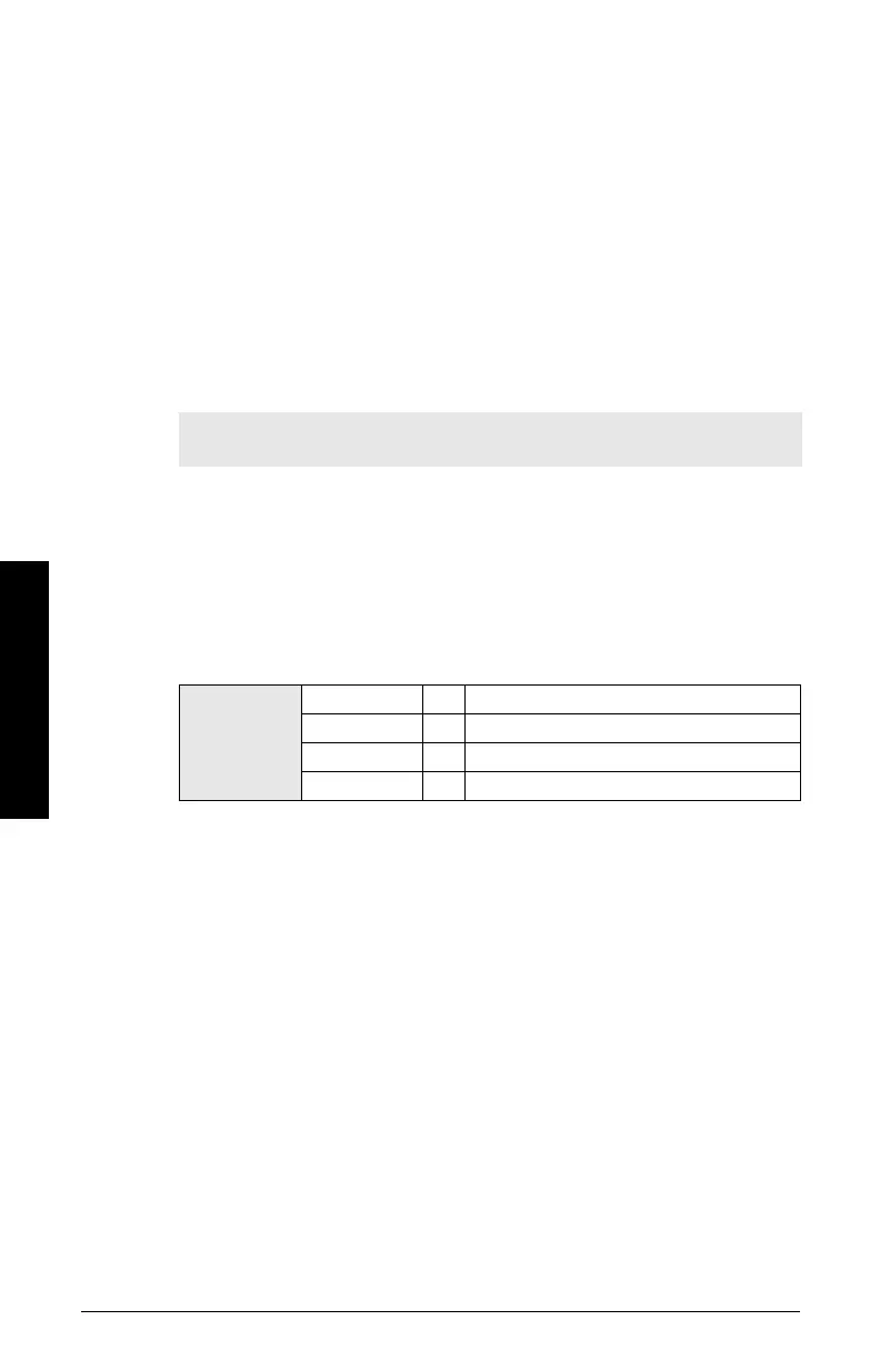
2.4.A. Temperature Units
Selects the engineering unit to be displayed with the value representing
temperature.
2.5. Measuring Limits
2.5.1. Min. Measured Value
The minimum recorded Sensor value, defined in Sensor units.
Open menu View – Peak Values, and click Sensor tab.
2.5.2. Max. Measured Value
The maximum recorded Sensor value, defined in Sensor units.
Open menu View – Peak Values, and click Sensor tab
Note: If a velocity calibration is performed after the sensor offset value has
been set manually, the sensor offset value will be reset to 0.
Hand
programmer
values
1034
Degrees K
1001 *
Degrees C
1002
Degrees F
1003
Degrees R
 Loading...