EasyManuals Logo
Home>Smartgen>Controller>ALC700 SERIES

Smartgen ALC700 SERIES User Manual

Smartgen ALC700 SERIES
51 pages
To Next Page IconTo Next Page
To Previous Page IconTo Previous Page
Page #30 background imageLoading...
Page #30 background image
ALC700 Series Light Tower Set Controller
ALC700 Series Light Tower Set Controller 2018-03-02 Version 1.4 Page 30 of 51
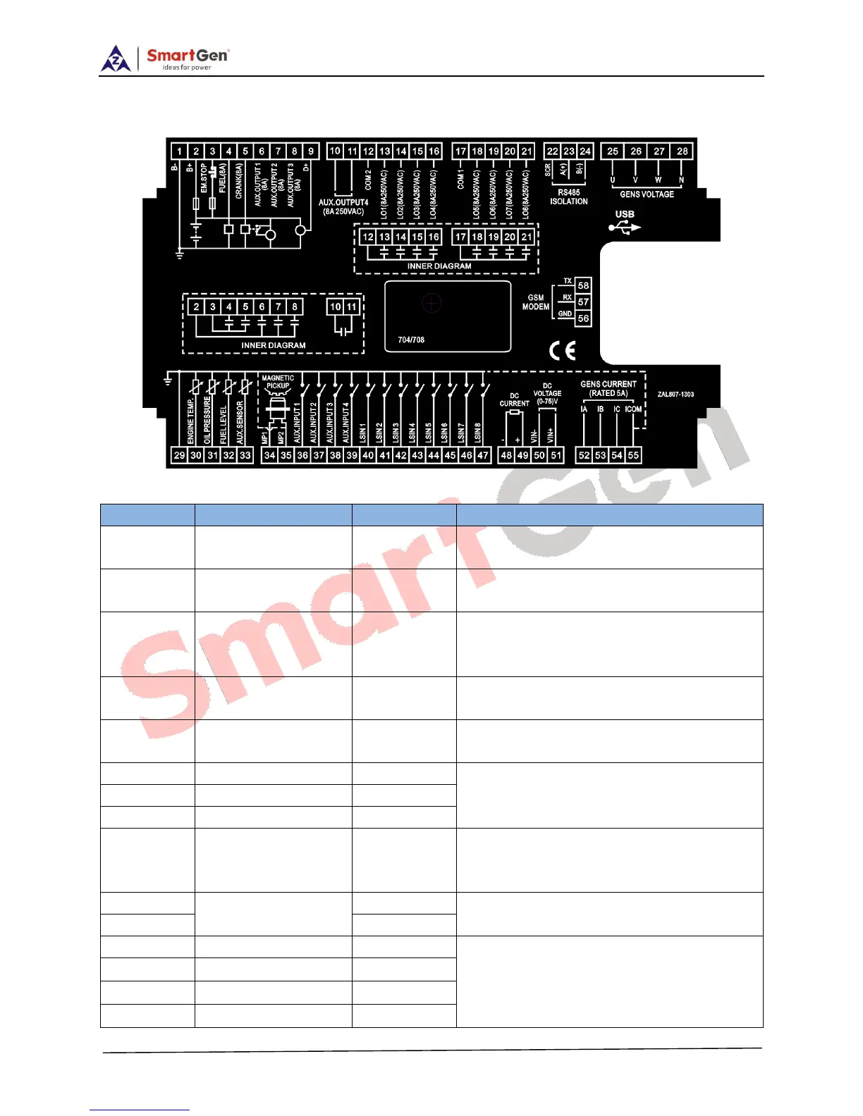
7 WIRING CONNECTION
ALC700 controller’s rear as following:
Description of terminal connection:
NO.
Functions
Cable Size
Remark
1
DC input B-
2.5 mm
2
Connected with negative of starter
battery.
2
DC input B+
2.5 mm
2
Connected with positive of starter battery.
20A fuse is recommended.
3
Emergency stop
1.5 mm
2
Connected with DC voltage via
emergency stop button. Max. 30A fuse is
recommended.
4
Fuel relay
1.5 mm
2
DC voltage is supplied by 3 point, rated
8A.
5
Start Relay
1.5 mm
2
DC voltage is supplied by 3 point, rated
8A.
6
Aux. output 1
1.5 mm
2
B+ outputrated 8A.
7
Aux. output 2
1.5 mm
2
8
Aux. output 3
1.5 mm
2
9
Charger (D+)
1.0 mm
2
Connected with charger’s D+ (WL)
terminals. Ground connection is not
allowed.
10
Aux. output 4
1.5 mm
2
Normally open voltage free outputs, rated
8A.
11
1.5 mm
2
12
1#-4# COM
2.5 mm
2
Total output current: 8A
If 1~4 is all used, the maximum current of
each light is 2A.
13
1# Light Output
1.5 mm
2
14
2# Light Output
1.5 mm
2
15
3# Light Output
1.5 mm
2

Questions and Answers:

Question and Answer IconNeed help?

Do you have a question about the Smartgen ALC700 SERIES and is the answer not in the manual?

Smartgen ALC700 SERIES Specifications

General IconGeneral
BrandSmartgen
ModelALC700 SERIES
CategoryController
LanguageEnglish

Related product manuals