ALC700 Series Light Tower Set Controller
ALC700 Series Light Tower Set Controller 2018-03-02 Version 1.4 Page 49 of 51
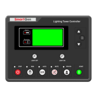
DC Generator Typical Wiring Diagram
NOTE: Users should select suitable Hall DC sensor according to the output power and
current of the light tower set.
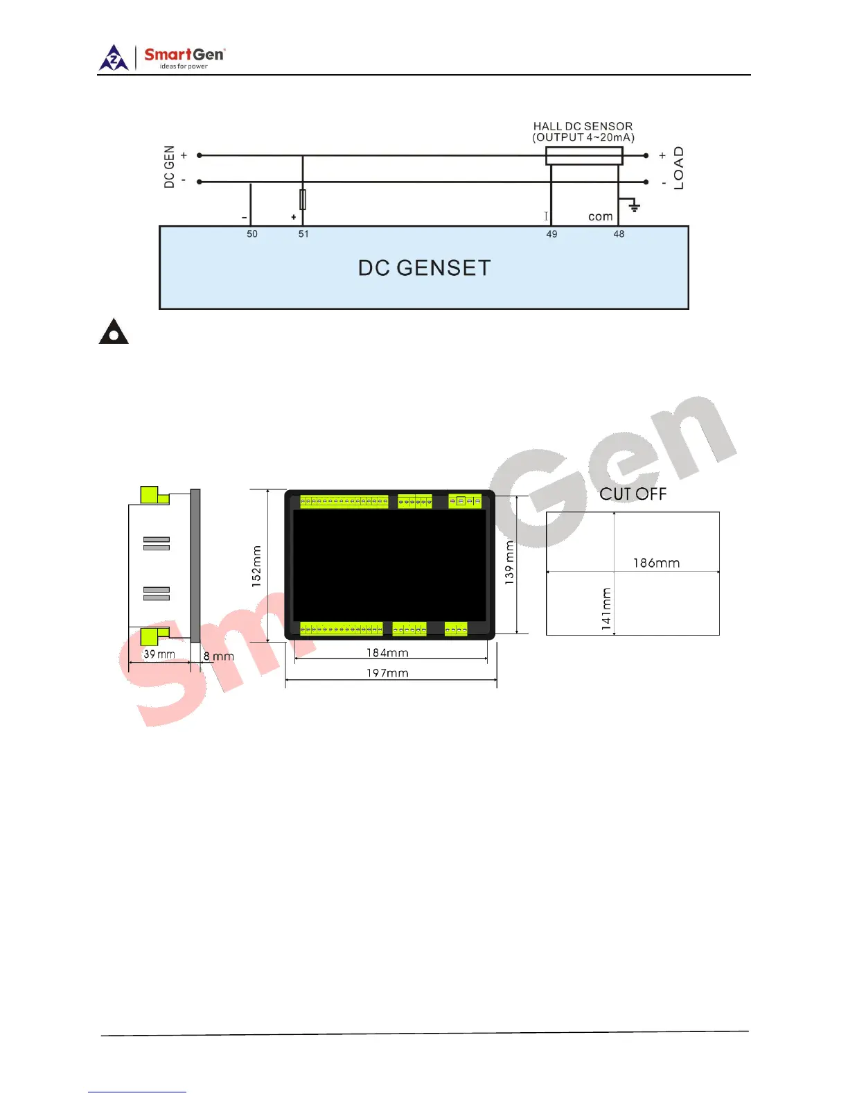
13 INSTALLATION
Controller is panel built-in design; it is fixed by clips when installed. The controller’s overall
dimensions and cutout dimensions for panel, please refers to as following,
13.1 BATTERY VOLTAGE INPUT
ALC700 controller can suit for widely range of battery voltage DC (8~35)V. Negative of battery
must be connected with the engine shell. The diameter of wire which from power supply to
battery must be over 2.5mm
2
. If floating charger is fitted, please firstly connect output wires of
charger to battery’s positive and negative directly, then, connect wires from battery’s positive
and negative to controller’s positive and negative input ports in order to prevent charge
disturbing the controller’s normal working.
13.2 SPEED SENSOR INPUT
Speed sensor is the magnetic equipment which be installed in starter and for detecting
flywheel teeth. Its connection wires to controller should apply for 2 cores shielding line. The
shielding layer should connect to No. 35 terminal in controller. The else two signal wires are
 Loading...