- 39 -
No.SFOD-OMT0010-B
(1) I/O1
-Input side
Connect the 24 VDC power supply to the input/ output signals
For IN0 to IN10, SETUP, HOLD, DRIVE, RESET, SVON
For OUT0 to OUT8, BUSY, AREA, SETON, INP, SVRE, ESTOP, ALARM
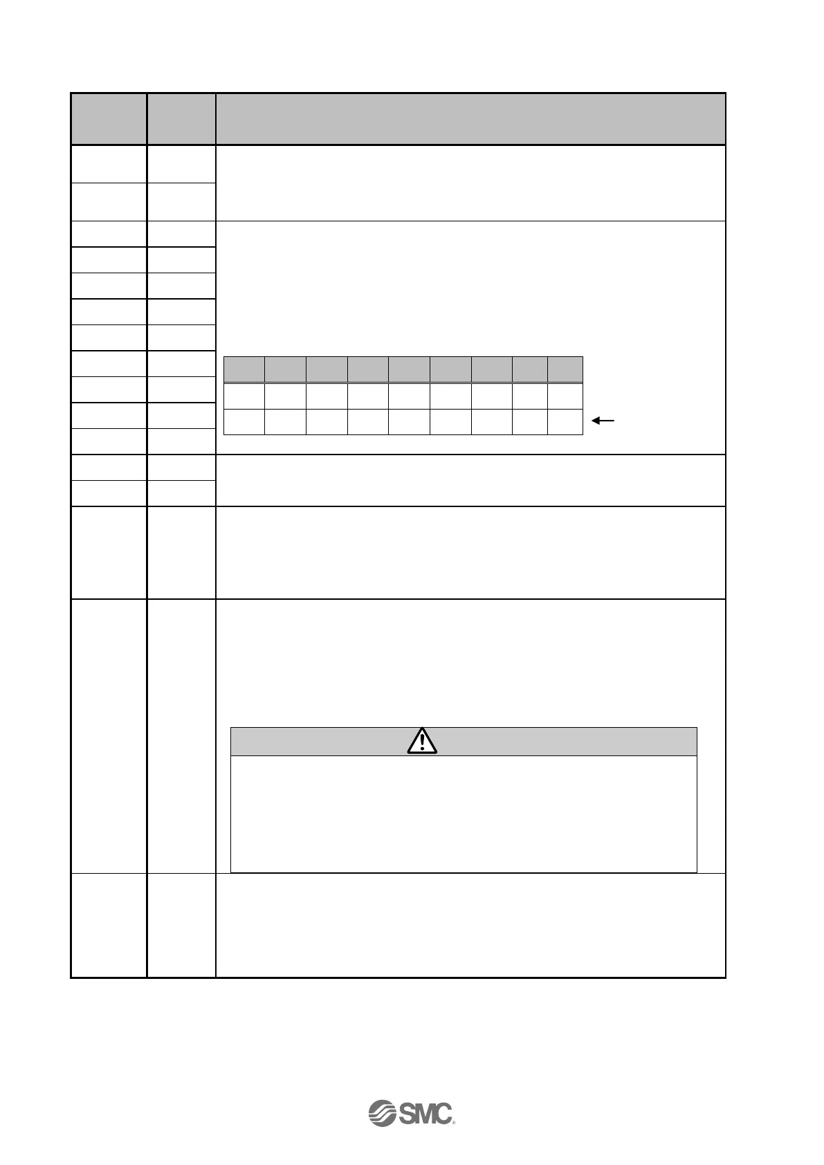
Step data instruction Bit No.(Standard: When 512 is used)
Step data instruction Bit No. (Input is instructed in the combination of IN0 to
IN8.)
Ex. (Assign step data No.3)
Step data instruction extended mode bit No (Extended: 2048 is used)
Command to Return to Origin
Actuators return to origin based on the order of setting for return to origin.
When SVRE output is ON, the SETUP operation (return to origin) will be
performed. During the SETUP operation, BUSY will be turned ON and after
completion of the SETUP operation, SETON and INP will be turned ON.
Pause of operation
All axes in operation are paused.
If HOLD input is ON during operation, the speed decreases at maximum
deceleration of the basic parameter until the actuator stops. The remaining
stroke will be on hold as long as HOLD is ON and when HOLD is turned OFF,
the actuator restarts to travel the remaining stroke.
(1) Do not command SETUP or DRIVE while the HOLD input is ON.
The actuator may make unexpected movements.
(2) While HOLD input is ON, do not move the actuator position.
Changing the residual travel distance may cause inconsistency with
the target position.
(3) HOLD input is invalid during return to origin operation.
Operation instruction
Read the step data from IN0 to IN8 while the DRIVE signal is ON and start
operation.
The number of ongoing steps is output to the OUT terminal when the DRIVE
signal is ON.

 Loading...


