- 80 -
No.SFOD-OMT0010-B
(7) Area output
-Procedures-
(a) Input the Step data No. (INx).
(b) Turn the "DRIVE" input ON. Step data No. 1 (OUTx output) will be output.
(c) The BUSY output will turn ON and INP output will turn OFF (the positioning operation will starts).
(d) The AREA output of step data No.1 turns ON (at 150mm from the origin point).
(e) The BUSY output will turn OFF and INP output will turn ON. (Positioning operation of step data
No.1 is completed).
(f) Input the step data No. 2 (INx).
(g) Turn the "DRIVE" input ON. Step data No. 2 (OUTx output) will be output.
(h) The AREA output will turn OFF. The BUSY output will turn ON and INP output will turn OFF. (The
positioning operation will start).
(i) The AREA output for step data No.2 will turnON (at 170mm from the origin point).
(j) The AREA output for step data No.2 will turnOFF (at 130mm from the origin point).
(k) The BUSY output will turn OFF and INP output will turn ON. (Positioning operation of step data
No.2 is completed).
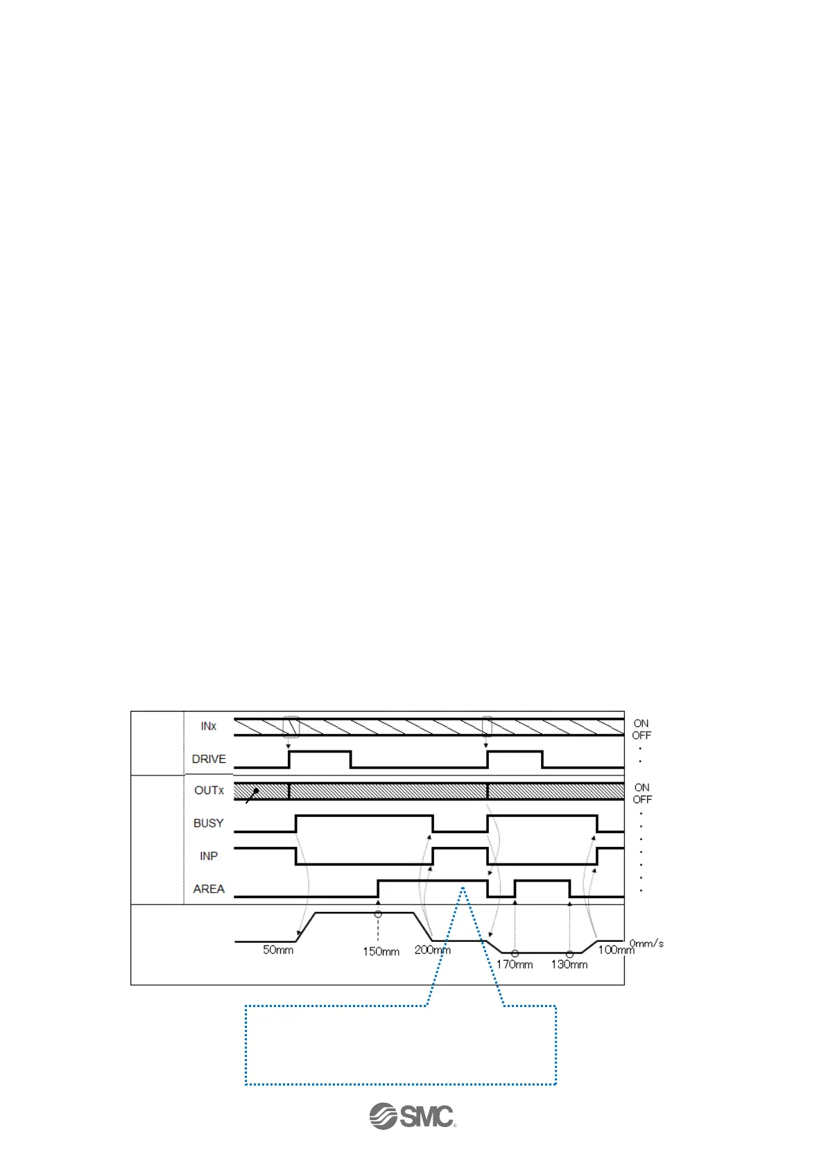
- Timing chart -
Initial position: 50mm
↓
Step data No.1 operation (Position: 200mm, Area 1: 150mm, Area 2: 250mm)
↓
Step data No.2 operation (Position: 100mm, Area 1: 130mm, Area 2: 170mm)
If the current position is within Area 1 and 2 of
step data, the AREA signal will turn ON.
Otherwise, the signal is OFF

 Loading...


