- 74 -
No.SFOD-OMT0010-B
9. Operation Instructions
9.1 Outline of the Operation instruction
The actuator is operated by selecting step data which is preset in the controller, using parallel I/O
signals. Refer to the following section for details of the parallel I/O signal timing and control
procedures.
9.2 Operation procedure of parallel I/O signals
Please refer to the following “Procedure” and “Timing chart” for each operation.
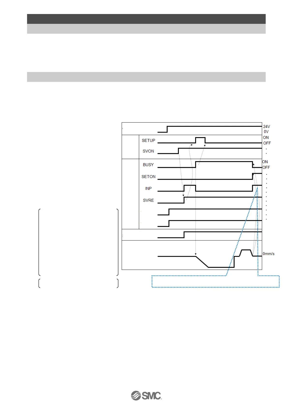
(1) From power on to Return to origin
- Procedure - - Timing chart -
(a) Turn the power supply ON
↓
(b) The
ALARM output turns ON.
ESTOP output is turned ON.
↓
(c) SVON input is turned ON.
↓
(d) SVRE output is turned ON.
INP output is turned ON.
The time taken for SVRE output
and INP output to turn on
depends on the actuator type
and the operating conditions.
(When power is supplied, it may
take up to 20 seconds from
servo ON to SVRE ON.)
Actuator (with lock) is unlocked.
↓
(e) Turn SETUP input ON.
↓
(f) BUSY output is turned ON and INP output is turned OFF (Starts the operation).
↓
(g) Return to origin is completed when the BUSY output is turned OFF and SETON and INP output
turns ON.

 Loading...


