IntroductionIntroduction
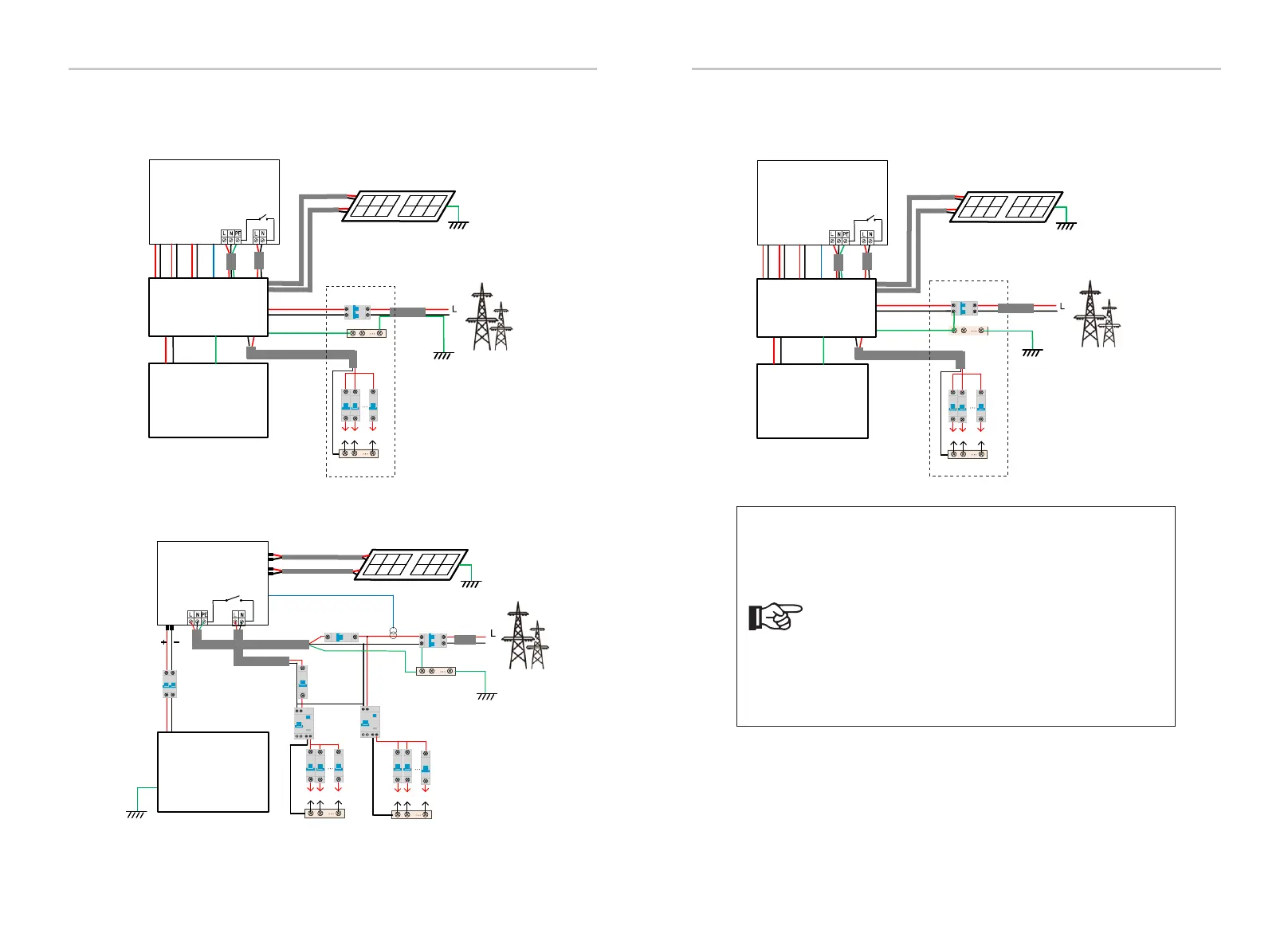
X1-Matebox
CT
Distribution Box
Battery
Grid
EPS
(Off-grid)
PV 1PV 2
E-BAR
Grid
Breaker
Loads
N-BAR for loads
N
Main Breaker
BAT
Inverter
14
15
Diagram B: Neutral line and PE line are separated from each other,
all loads connect to the EPS(Off-grid) port; (For most countries)
Diagram C: Neutral line and PE line are combined together, and the
common load is connected to the EPS(Off-grid) port;
(Apply to Australia)
X1-Matebox
CT
Distribution Box
Battery
Grid
PV 1PV 2
E-BAR
Grid
Breaker
Loads
N-BAR for loads
Main Breaker
BAT
Inverter
EPS
(Off-grid)
N
PE
Diagram D: Neutral line and PE line are combined together, all
loads connect to the EPS(Off-grid) port; (Apply to Australia)
Notice!
• When power cuts suddenly, the inverter connects the
N line of EPS(Off-grid) load with the ground through
relay, providing a fixed zero potential for EPS(Off-grid)
load and ensuring the safety of electricity use by users.
• Please control the inverter load and make sure it is
"output value" in "within " EPS(Off-grid) mode, otherwise
the inverter will stop and alarm overload fault".
• Please confirm with the grid operator whether there
are special regulations for grid connection.
N
BAT
Battery
N-BAR for loads
N-BAR for EPS(Off-grid) loads
EPS(Off-grid) loads
Loads
Inverter
PV 1
PV 2
E-BAR
RCD
Breaker
Grid
Breaker
Grid
EPS(Off-grid)
Main Breaker/RCD
Breaker
Breaker
CT
CT
Breaker
RCD

 Loading...