Electrical Connections
Table 1: Maximum input voltage limit
Warning!
6.1 PV Connection
Notice!
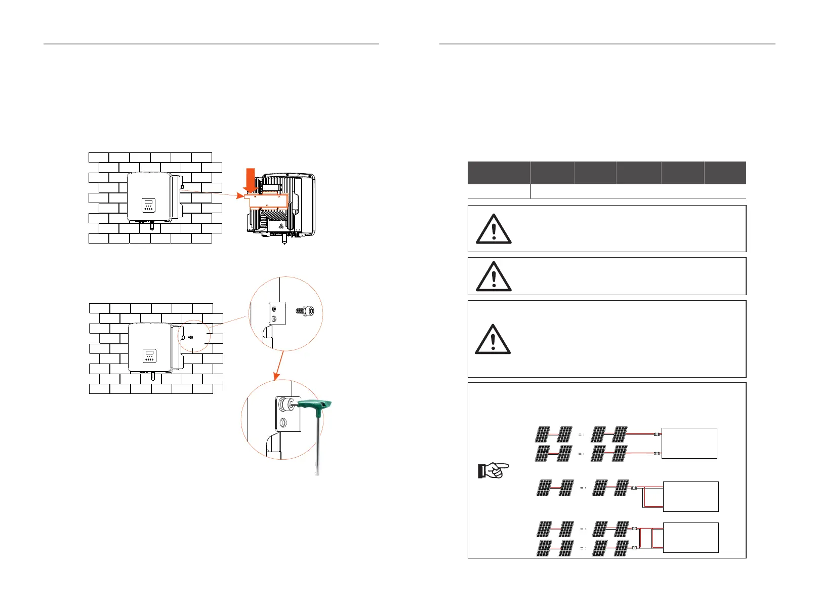
The series inverters support the following PV module
connection modes.
Max. DC input voltage
600 V
6 Electrical Connections
e)
f)
Ø Step 3: Tighten the inverter and bracket
Inner hexagonal wrench
(Torque :1.2±0.1 N· m)
Installation
34
35
PV 1PV 1
+
-
PV 2
+
-
PV 1
+
-
PV 2
+
-
+
-
PV 1PV 1
+
-
PV 2
+
-
PV 1
+
-
PV 2
+
-
PV 1PV 1
+
-
PV 2
+
-
PV 1
+
-
PV 2
+
-
Method 2: Comm
Method 1: Multi
Inverter
PV
Inverter
Inverter
Inverter
e) Hang the buckle on the inverter to the corresponding position of the
backplane;
f) Use the inner hexagonal wrench to tighten the inner hexagonal screw on
the right side of the inverter.
The series inverter have two PV inputs. Please select photovoltaic
modules with good performance and quality assurance. The open circuit
voltage of the module array should be less than the maximum PV input
voltage specified by the inverter, and the working voltage should be
within the MPPT voltage range.
Warning!
The voltage of photovoltaic modules is very high, and is
dangerous voltage. When wiring, please follow the safe
electricity regulations.
Do not ground the positive or negative pole of the
photovoltaic module!
Notice!
The following PV module requirements need to be applied
to each input range:
1. Same model
2. Same quantity
3. The same queue
4. The same angle
PV 1PV 1
+
-
PV 2
+
-
X1 HYD G4
PV 1
+
-
PV 2
+
-
Inverter
PV 1PV 1
+
-
PV 2
+
-
PV 1
+
-
PV 2
+
-
Inverter
Model
X1-Hybrid-3.0-D
X1-Hybrid-3.0-M
X1-Hybrid-3.7-D
X1-Hybrid-3.7-M
X1-Hybrid-6.0-D
X1-Hybrid-6.0-M
X1-Hybrid-7.5-D
X1-Hybrid-7.5-M
X1-Hybrid-5.0-D
X1-Hybrid-5.0-M
X1-Hybrid-5.0K-D
X1-Hybrid-3.0-D
X1-Hybrid-3.0-D
 Loading...